DIY Engine Simulator for ECU Bench Testing
A comprehensive guide to building a DIY hardware Engine Simulator for bench-testing and debugging Honda OBD0, OBD1, and OBD2 ECUs.
An Engine Simulator (ECU stimulator or bench jig) is an essential tool for hardware developers and tuners. It simulates the electrical loads and sensor signals of a running vehicle, allowing you to operate an ECU on a workbench to test custom firmware, diagnose component-level hardware failures, or verify circuit modifications without risking damage to a vehicle.
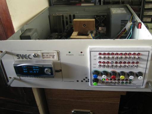
This guide details a rack-mountable engine simulator design that utilizes a combination of real automotive components, load-simulating power resistors, and variable signal generators to replicate a complete Honda OBD1 PGM-FI engine harness.
Simulator Subsystems & Load Components
To prevent the ECU from triggering error codes, the simulator must mimic the electrical behaviors and loads of real solenoids, heaters, and injectors.
Actuator & Load Simulation
- Injectors: Uses four 12Ω 5W power resistors to simulate injector coil impedance, preventing Code 16 (Fuel Injector System).
- EACV / IACV: An actual Idle Air Control Valve is wired into the system to load the ECU's idle control circuit.
- VTEC Solenoid (VTS): A real VTEC solenoid is mounted to the chassis to provide audible confirmation of VTEC engagement.
- VTEC Pressure Switch (VTP): Simulated using a relay coil driven by the VTS output signal, closing the switch to ground upon activation.
- Oxygen Sensor Heater: Simulated using three 3.7kΩ 5W resistors wired in parallel to dissipate heat safely.
- Fuel Pump: An inline bi-color LED indicates when the fuel pump relay is primed and running.
- Main Relay: A standard Honda 7-pin Main Relay is integrated to distribute power to the board and ECU.
Sensor Input Simulation
- Analog Sensors (TPS, MAP, ECT, IAT, EGR): Simulated using high-quality variable rotary potentiometers to sweep voltages between
0Vand5V. - Electric Load Detector (ELD): An actual ELD unit is wired in series with the main power distribution lines, allowing the ECU to read real-time current load fluctuations.
- Knock Sensor: A real knock sensor is mounted to the metal chassis; tapping the chassis allows for testing of knock board detection routines.
Distributor & Engine Speed Simulation
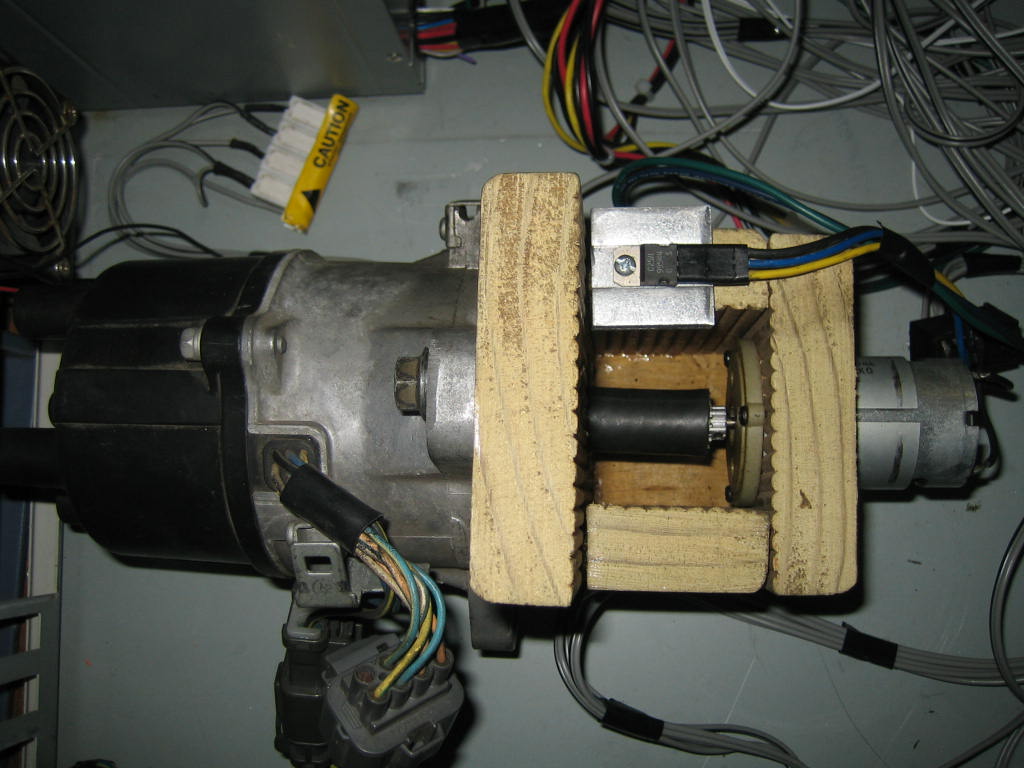
Simulating engine speed (RPM) requires synchronized pulse inputs for the CKP (Crankshaft Position), TDC (Top Dead Center), and CYP (Cylinder Position) sensors. This simulator uses a physical OBD1 distributor driven by an electric motor.
Assembly Details
- Drive Motor: A 12V motor salvaged from a cordless drill.
- Speed Control: The drill's trigger switch is wired to a rotary potentiometer to vary motor speed (500â9,000+ RPM).
- Coupling: The distributor shaft is coupled to the motor using a 15-tooth RC car gear and heavy-duty rubber fuel hose to absorb vibrations.
- Ignition Coil & ICM: The Ignition Control Module (ICM) and ignition coil are wired into the distributor housing. 12V power is supplied to the black/yellow lead from the main relay to prevent Code 15 (Ignition Output Signal).
Tip
Physical distributors provide excellent mechanical feedback, but they may stall at very low speeds (under 500 RPM) if the motor lacks torque, effectively simulating an engine stall.
Control Panel Interface
The control panel allows the operator to manipulate sensor inputs and inject faults into the system.
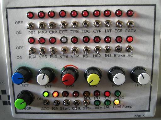
Control Panel Features
- Sensor Adjustment Knobs: Dials for ECT, IAT, RPM, VSS, TPS, MAP, and EGR.
- Fault Toggles: SPST switches wired in series with critical sensor lines to trigger specific Diagnostic Trouble Codes (DTCs).
- Indicator LEDs: Bi-color LEDs display circuit status (e.g., A/C clutch relay engagement).
- Ignition Switches: Emulates standard key positions (Accessory, Ignition, Start). The Start switch automatically engages the distributor drive motor.
ECU & Harness Interface
The chassis features a modular interface scheme to ensure compatibility across different ECU generations.
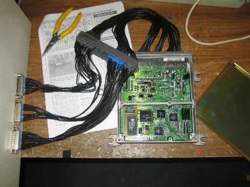
- DB25 Connectors: Three DB25 ports are mapped to standard OBD1 ECU pins (Plugs A, B, and D).
- Interchangeable Harnesses: Custom adapter harnesses (DB25 to OBD0, OBD1, OBD2a, or OBD2b) allow for rapid switching between ECU generations.
Wiring Schematics
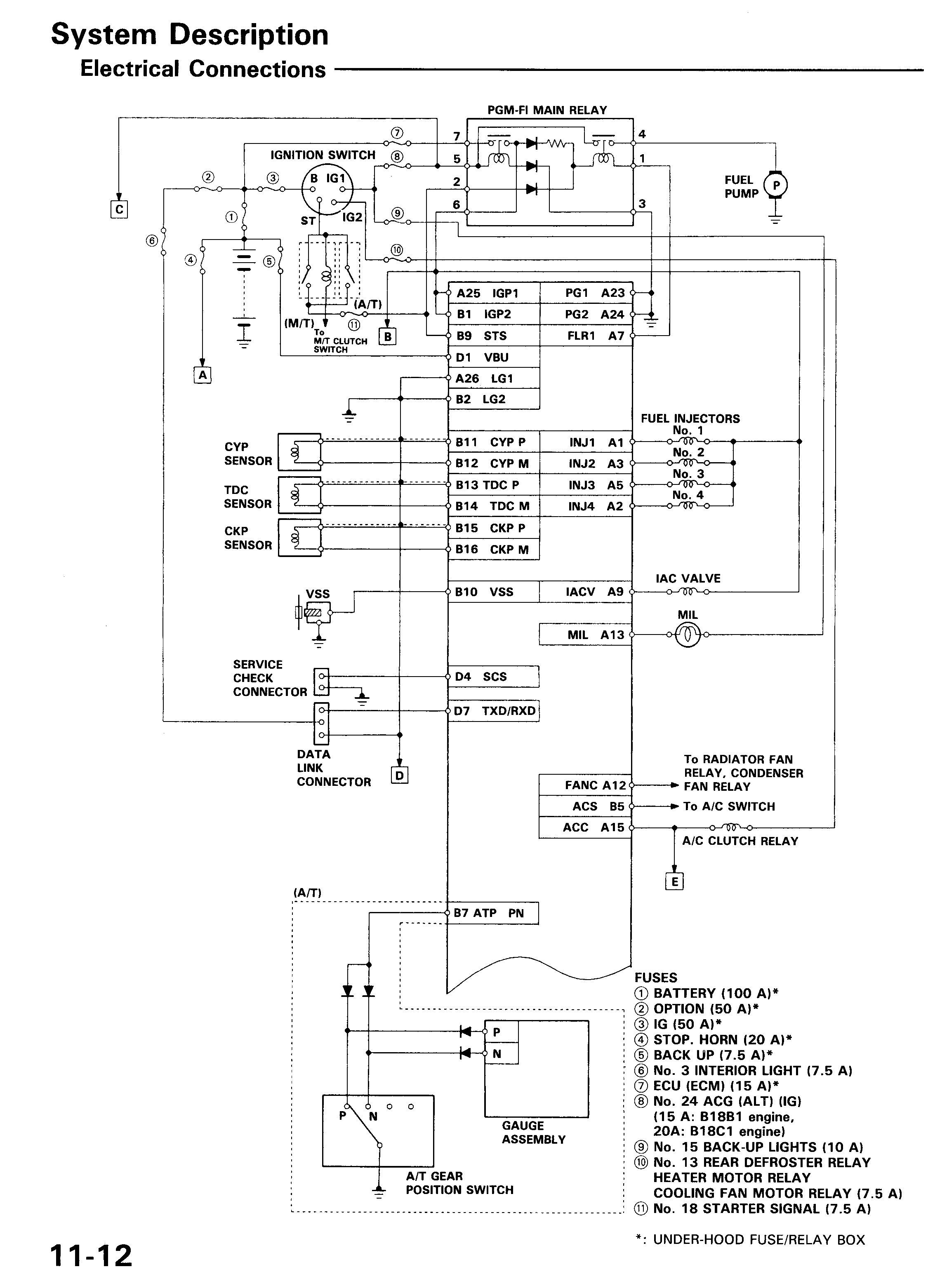
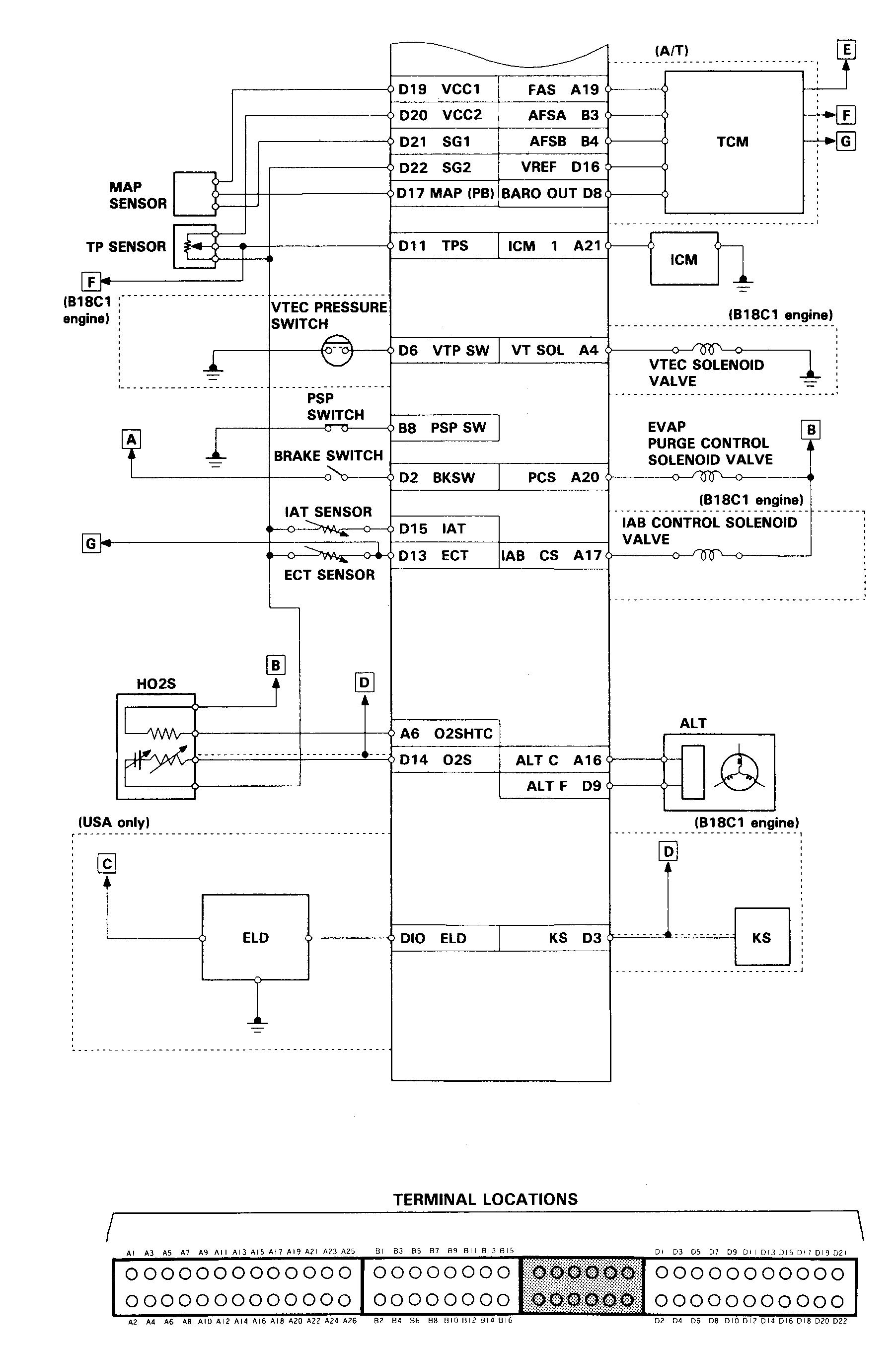
The simulator is wired according to standard OBD1 Civic/Integra PGM-FI pinouts.
| Component | Pinout Reference |
|---|---|
| Outputs | PGM-FI Pinout Part 1 |
| Sensors/Distributor | PGM-FI Pinout Part 2 |