Easy-RTP v1.0 OBD1 Installation Guide
Technical installation procedure for integrating the Easy-RTP v1.0 module into OBD1 P28 and P30 ECUs.
This guide details the installation of the Easy-RTP v1.0 board into OBD1 ECUs. The process involves interrupting the CPU write-enable circuit and interfacing the RTP board with the required address and write signals.
Warning
This procedure requires severing a factory PCB trace and soldering directly to integrated circuit (IC) pins. Verify all signal paths and pinouts against your specific ECU board revision before applying power.
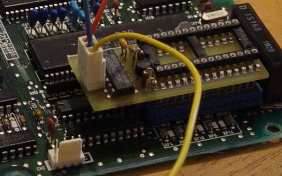
Ensure the Easy-RTP v1.0 module is fully assembled before beginning the installation.
Removable Connection Strategy
To maintain the ability to revert to a standard ROM, the installation utilizes a removable plug system. This allows a jumper plug to reconnect the original factory circuit when the RTP board is removed.
- Wiring: Use small-gauge wire (e.g., wire-wrap wire) to accommodate the tight clearances of the ECU housing.
- Header: A right-angle header on the RTP board is recommended to provide sufficient clearance for the ECU case.
P28 Installation Procedure
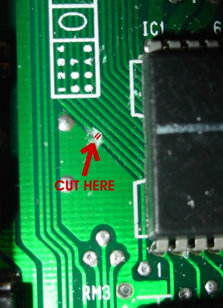
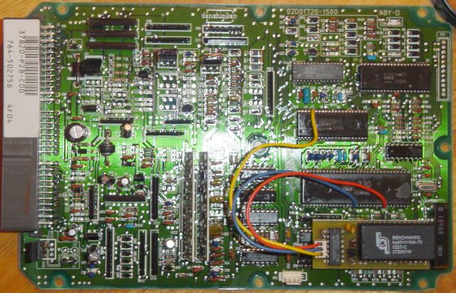
- Isolate Trace: Locate and sever the MCU
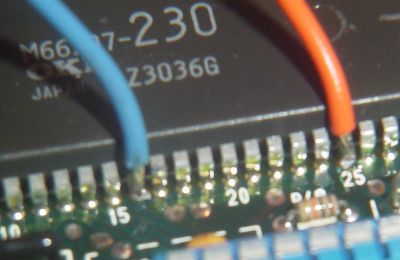
WE(Write Enable) trace as indicated in the reference imagery. - Address Line: Connect the RTP board
A15wire to MCU Pin 16. This address line is typically unused and is required to address the writable ROM image. - Write Enable (MCU Side): Connect the MCU side of the severed
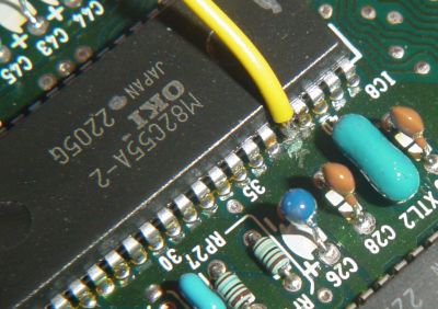
WEtrace (MCU Pin 25) to theWE interminal on the RTP board. Tin both the IC pin and the wire prior to soldering to ensure a secure bond. - Write Enable (Peripheral Side): Connect the remaining side of the severed write-enable circuit to Pin 38 of the M82C55A. This configuration ensures the RTP board enables NVSRAM writes only when
A15is high. - Verification: Inspect all solder joints for bridges or cold joints. Confirm the severed trace is fully isolated before applying power.
JDM Surface-Mount Pin Reference
For JDM P30-900 ECUs utilizing surface-mount components, use the following pin mapping:
| Signal | Surface-Mount Pin | DIP Pin (Standard) |
|---|---|---|
| A15 (on M66207) | 17 | 16 |
| WE/WR (on M66207) | 27 | 25 |
| WE/WR (on 82C55) | 40 | 38 |
Restoring the Original Path
The installation routes the two halves of the severed write-enable circuit to connections 1 and 3 on the RTP board. When the RTP module is removed, a dummy jumper plug must be installed to bridge these two wires, restoring the original factory circuit for standard ROM operation.
Caution
Always verify connector numbering and continuity with a multimeter before operation. An incorrectly wired jumper can cause short circuits or leave the write-enable path open, preventing the ECU from functioning.
Datalogging Interface
Once the hardware is installed, an RS232-to-TTL converter is required for ECU-to-PC communication. Refer to the following resources for interface configuration:
- {{> datalogging-overview }}
- {{> serial-communication-guide }}