Logging an external 0-5 V sensor through P30 D12
Archived USDM P30 D12 analog-input method for logging an external 0-5 V sensor.
Adapted from pgmfi.org wiki
This archived method uses the undocumented D12 analog input on a USDM OBD1 P30 ECU to record an external 0-5 V signal, such as the output from an EGT amplifier or wideband O2 controller.
Warning
The source only documents direct testing on a USDM P30. It suggests that other USDM OBD1 ECUs should share the circuit and says a USDM P28 appears similar, but leaves that compatibility unconfirmed. JDM P30 ECUs use a different, incomplete D12 circuit.
D12 analog input
On the documented USDM P30, D12 leads to the 66207's AI3 input at Pin 57. The archived schematic identifies the analog-input circuit around that connection.
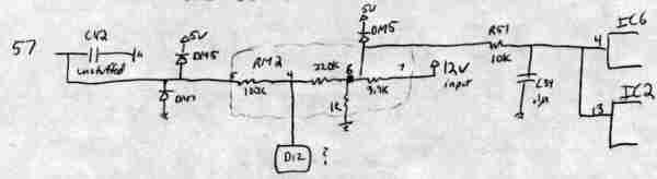 Archived schematic of the USDM P30 analog-input section.
The source describes the logged data as follows:
| Item | Archived description |
|---|---|
| Input range | 0-5 V applied at D12 |
| Main logged byte | RAM 0067h |
| Main-byte scale | Approximately 0.02 V per count, from 00h at 0 V to 0FFh at 5 V |
| Additional ADC bits | RAM 0066h contains the two least-significant bits of the 10-bit ADC result |
| Reported signal loss | About 1% from D12 to AI3 at 66207 Pin 57 |
The author considered the extra two ADC bits unnecessary for EGT logging. The page reports the voltage loss but does not document how it was measured or provide calibration data.
Optional C42 filter from the source
The stock USDM ECU documented by the source had no component installed at C42. The archived recommendation was to install a 1 uF, 35 V tantalum capacitor there to smooth the ADC input, with its positive side facing away from the 66207 and matching the orientation of the other capacitors in that row.
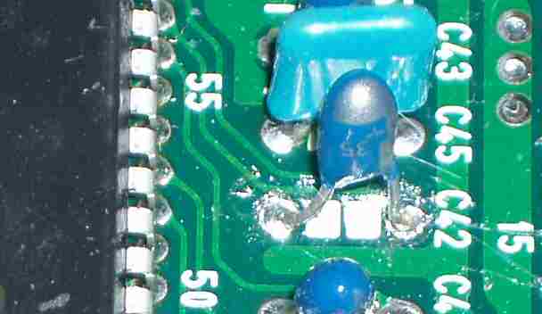 Archived photo showing the added
 C42 capacitor.
Warning
Capacitor polarity and board layout must be verified on the actual ECU. The archived recommendation was not documented for every P30 board revision or other ECU type.
JDM P30 difference
The source says the USDM P30 grounds AI5, while the JDM P30 grounds AI3 and routes D12 to AI5 at 66207 Pin 63. The JDM D12 path also has uninstalled components and must be modified before it can be used as described.
See the archived JDM P30 D12 modification for the circuit changes and its unresolved AI5 software caution.
Uses described by the source
The archived page discusses these possible uses for D12:
- EGT logging from a thermocouple amplifier with a 0-5 V output.
- Wideband O2 logging while leaving the stock narrowband O2 input unchanged.
- A software-interpreted switch input with a pull-up resistor.
The switch idea was only a programming concept in the source. It would also consume D12, preventing simultaneous EGT or other external-sensor logging.
Related
Credits and source
Authors markolson
Source Adapted from How To Log External Data Such As An Egt Sensor on pgmfi.org wiki. Licensed under CC BY-NC-SA 1.0.