OBD0 Honda PW0 ECU Reference Guide
A comprehensive hardware and software reference guide for the JDM and European OBD0 PW0 DOHC VTEC ECU, including ROM address calibrations and mapping.
The PW0 Engine Control Unit (ECU) is an OBD0 controller utilized in JDM and European-market vehicles from 1989 to 1991. It was standard equipment in the JDM Civic SiR (EF9), CRX SiR (EF8), and Integra XSi/RSi (DA6), managing the first-generation DOHC VTEC 1.6L B16A engine.
Overview
The PW0 features a robust internal architecture utilizing an OKI-based microcontroller and dual knock sensor inputs on JDM variants. This guide outlines critical ROM address locations for modifying parameters, including checksums, VTEC crossovers, and rev limits.
ECU Board Scans
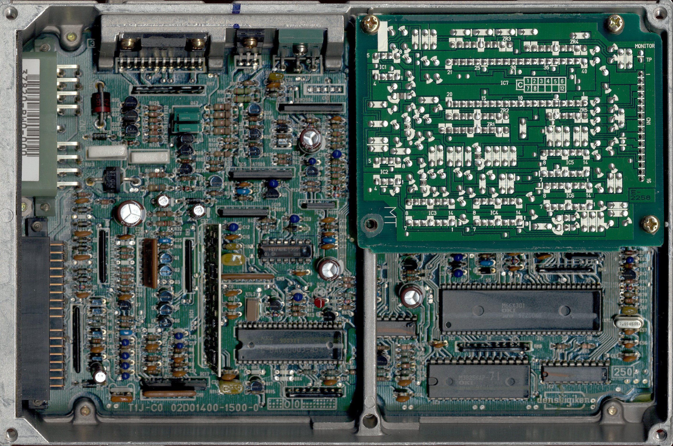
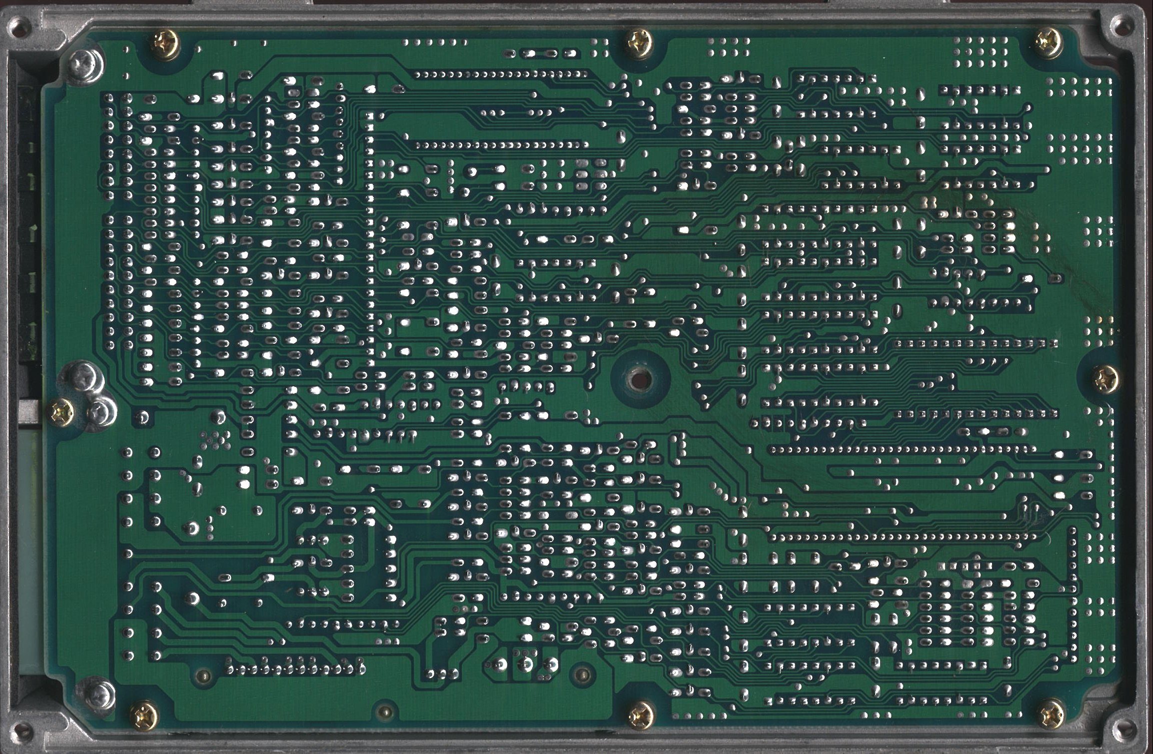
JDM PW0 ROM Address Map
The following table details hex address offsets within the EEPROM for standard JDM PW0-000 calibrations.
| Location | Bytes | Description | Notes |
|---|---|---|---|
| 20B2 | 1 | Checksum Bypass | Change 0xC9 to 0xCB to bypass checksum |
| 391A | 1 | High Cam Rev Limiter | Warm/VTEC engine RPM fuel cut |
| 391C | 1 | Low Cam Rev Limiter | Low cam engine RPM fuel cut |
| 3922 | 1 | High Cam Rev Recovery | RPM where VTEC fuel cut recovers |
| 3AD8 | 1 | VTEC Disengage Speed | Lower VTEC cut-off speed threshold |
| 3AD9 | 1 | VTEC Engage Speed | VTEC engagement speed threshold |
| 3ADA | 1 | VTEC Disengage RPM | Crossover low RPM hysteresis limit |
| 3ADB | 1 | VTEC Engage RPM | Crossover high RPM activation point |
| 3BE6 | 255 | Low Cam Ignition Map | 15x17 low cam ignition advance map |
| 3CE5 | 255 | High Cam Ignition Map | 15x17 VTEC ignition advance map |
| 3DE4 | 255 | Low Cam Fuel Table | 15x17 base fueling lookup map |
| 3EE3 | 15 | Low Cam Multipliers | Column multiplier coefficients |
| 3EF2 | 255 | High Cam Fuel Table | 15x17 VTEC fueling lookup map |
| 3FF1 | 15 | High Cam Multipliers | Column multiplier coefficients |
European PW0 ROM Address Map
The following table details hex address offsets within the EEPROM for European-spec PW0 calibrations.
| Location | Bytes | Description | Notes |
|---|---|---|---|
| 1F21 | 1 | Checksum Bypass | Change 0xC9 to 0xCB to bypass checksum |
| 3928 | 1 | High Cam Rev Limiter | Warm/VTEC engine RPM fuel cut |
| 392A | 1 | Low Cam Rev Limiter | Low cam engine RPM fuel cut |
| 3930 | 1 | High Cam Rev Recovery | RPM where VTEC fuel cut recovers |
| 3AEC | 1 | VTEC Disengage Speed | Lower VTEC cut-off speed threshold |
| 3AED | 1 | VTEC Engage Speed | VTEC engagement speed threshold |
| 3AEE | 1 | VTEC Disengage RPM | Crossover low RPM hysteresis limit |
| 3AEF | 1 | VTEC Engage RPM | Crossover high RPM activation point |
| 3BE6 | 255 | Low Cam Ignition Map | 15x17 low cam ignition advance map |
| 3CE5 | 255 | High Cam Ignition Map | 15x17 VTEC ignition advance map |
| 3DE4 | 255 | Low Cam Fuel Table | 15x17 base fueling lookup map |
| 3EE3 | 15 | Low Cam Multipliers | Column multiplier coefficients |
| 3EF2 | 255 | High Cam Fuel Table | 15x17 VTEC fueling lookup map |
| 3FF1 | 15 | High Cam Multipliers | Column multiplier coefficients |
Fuel Column Multiplier Formula
Because 8-bit cell values (0â255) provide limited resolution, the PW0 ECU applies a column-specific multiplier coefficient to each load column.
$$\text{Column Multiplier} = \frac{2^{\text{Multiplier Value}}}{4}$$
Important
The final calculated injector pulse-width uses this multiplier to scale the raw fuel map cell value into the final injection duration. Refer to the fuel mapping documentation for specific load scaling procedures.