Remove A Knock Sensor
Removing the knock detection is simple: Resolder R118 and R119 into R142, 143. Then, Remove R101 (optional).
Adapted from pgmfi.org wiki
Removing the knock detection is simple: Resolder R118 and R119 into R142, 143. Then, Remove R101 (optional). Finally, remove the knock board itself.
- no_knock.jpg:
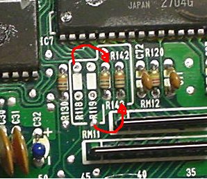
Here's what a knockless P14 looks like: CLick Here!0Originaly posted by prelude-driverhere is how it works, R101 is a current limit to a signal on the KS, you need it with KS but you can leave it in because it does not go anywhere else. R118/119 are current limiters on the clock & data signals to the KS, if you remove the KS you must remove them because of the next resistors. R142/143 are pullup resistors for the clock & data lines, you dont use them if you have a KS because there are pullups on the KS itself, but if the KS is removed then you must fit these to stop the lines from floating. they are 10k btw.
Applies to
1 taxonomy linkHonda
1 linkCredits and source
Source Adapted from Remove A Knock Sensor on pgmfi.org wiki. Licensed under CC BY-NC-SA 1.0.