JDM Honda/Acura 180 km/h Speed Limiter VSS Signal Conditioner
This article details the operation and installation principles of a JDM Honda/Acura 180 km/h speed limiter signal conditioner, which modifies the Vehicle Speed Sensor (VSS) signal to bypass the factor
Adapted from Icelord

JDM (Japanese Domestic Market) Honda and Acura vehicles are typically equipped with an electronic speed limiter, restricting the vehicle's maximum speed to approximately 180 km/h (112 mph). This limitation is enforced by the Engine Control Unit (ECU) based on the Vehicle Speed Sensor (VSS) signal. A VSS signal conditioner, often referred to as a "speed limiter defencer," is an electronic module designed to modify this signal, allowing the vehicle to exceed the factory-imposed speed limit.
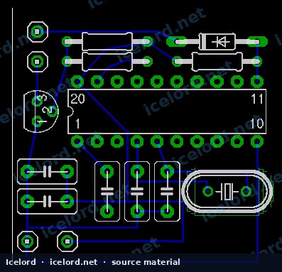
Image placeholder - replace with a publication-cleared photo (vss.png).
Theory of Operation
The VSS signal conditioner operates by intercepting the raw VSS signal from the transmission and conditioning it before it reaches the ECU. The VSS generates a square wave signal with a 50% duty cycle, where the frequency directly corresponds to vehicle speed.
The device continuously monitors the incoming VSS frequency. When the vehicle speed is below a certain threshold (approximately 170 km/h or 119 Hz), the conditioner acts as a pass-through, transmitting the authentic VSS signal directly to the ECU. Once the actual vehicle speed exceeds this threshold, the module switches to a "virtual mode." In this mode, it generates and outputs a simulated VSS signal to the ECU, typically capped at a frequency equivalent to the threshold speed (e.g., 119 Hz). This tricks the ECU into believing the vehicle is still operating below the 180 km/h limit, preventing fuel cut-off or other limiter-induced interventions.
Vehicle Speed Sensor (VSS) Signal Characteristics
The VSS signal frequency scales linearly with vehicle speed. The following are approximate frequencies for common speeds:
| Speed (km/h) | Speed (mph) | VSS Frequency (Hz) | Duty Cycle |
|---|---|---|---|
| 60 | 37 | 42 | 50% |
| 100 | 62 | 70 | 50% |
| 120 | 75 | 84 | 50% |
| 170 | 106 | 119 | 50% |
Note
These values are typical for many Honda/Acura VSS systems. Always confirm specific VSS characteristics for your vehicle model and year using the factory service manual.
Installation Principles
Installing a VSS signal conditioner involves integrating the module into the vehicle's existing VSS wiring harness. The device typically requires connections for input, output, power, and ground.
Required Connections
- VSS Input: Connects to the original VSS signal wire coming from the transmission.
- VSS Output: Connects to the VSS signal wire leading to the ECU.
- Power (12V): Connects to a switched 12-volt power source.
- Ground: Connects to a reliable chassis ground point.
Important
The specific VSS wire color, pin location at the ECU, and optimal installation point vary significantly between Honda/Acura models and generations. Always consult the factory service manual (FSM) for your exact vehicle to identify the correct VSS wire. Incorrect wiring can lead to ECU damage or vehicle malfunction.
General Installation Steps
- Locate the VSS Wire: Identify the VSS signal wire leading to the ECU. This is often found at the ECU connector itself or within the engine bay harness.
- Cut the VSS Wire: Carefully cut the VSS signal wire at a suitable location.
- Wire the Conditioner:
- Connect the VSS wire coming from the transmission to the conditioner's VSS input.
- Connect the VSS wire going to the ECU to the conditioner's VSS output.
- Connect the conditioner's power wire to a switched 12V source.
- Connect the conditioner's ground wire to a chassis ground.
- Secure the Module: Mount the signal conditioner securely in a location protected from moisture and excessive heat.
- Test Functionality: After installation, test the vehicle's speedometer and ensure proper operation at all speeds, including above the original limiter threshold.
Caution
Improper wiring can cause damage to the ECU, the VSS, or the signal conditioner itself. Ensure all connections are secure, insulated, and correctly oriented.
Internal Components
While specific designs may vary, these devices commonly utilize a microcontroller, such as the Atmel AT89C4051, to process and condition the VSS signal. The microcontroller's firmware is programmed to implement the logic for real signal pass-through and virtual signal generation based on the input frequency.
Note
This article describes the general principles of a common JDM speed limiter defencer. Specific implementations may differ. For detailed schematics or programming information, refer to the manufacturer's documentation for your specific device.
Applies to
6 taxonomy linksCredits and source
Source Adapted from JDM HONDA 180km/h Speed Limiter remover on Icelord. Licensed under All rights reserved.