Powering an ODB1 ECU on the Bench

JaredKaragen

#31 โ—ˆ 2017-08-08

Re: Powering an ODB1 ECU on the Bench

Type-GS-R-Turbo wrote:
Sweet! I'm going to use that as a reference, I'll let you know how it works out.


Let me know when I can pick one up from you... I would love one of these; I can paypal some cash now if you want.... as in tonight =P

but; I would suggest a feature; one for the A17 AT lockup outputs as eCtune uses that for PWM too, and is the only way to PWM on a JDM ECU =)


I love it...


and


You sir;


are


THE MAN!

Type-GS-R-Turbo

#32 โ—ˆ 2017-08-08

Re: Powering an ODB1 ECU on the Bench

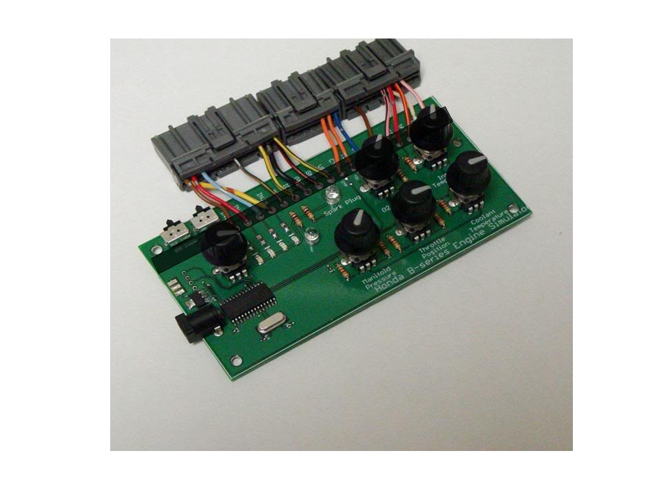
Hey guys, I just posted the engine sim on Moates. I am taking pre-orders to fund the new version that supports VTEC and PWM.

So go ahead, buy my stuff!! (Shameless plug LOL)

http://www.moates.net/product_info.php?cPath=50&products_id=198

7rrivera7

#33 โ—ˆ 2017-08-08

Re: Powering an ODB1 ECU on the Bench

I'm super interested but I think you should re-evaluate the way you connect the ECU plugs to your board.

I'm concerned that after multiple insertions and removals from the ECUs the wires will start to come off of their solder joints. Maybe reinforcement in the area they are soldered in with some type of a cover which wraps around this area on the whole board, securing the wires to the board will help? (see pic)

Image

Another option would be to use a mating connector between the ECU plugs and the board. This way we could plug the wires into the ECU first then 'snap' them into the mating connector on the board. This will probably add more cost to the SIM but I think it will last longer.

My 2 cents...

Type-GS-R-Turbo

#34 โ—ˆ 2017-08-08

Re: Powering an ODB1 ECU on the Bench

I should have probably mentioned that in the final revision there are 6" of wires between the plugs and the ECU. So yeah, I did think of that. The connector would be somewhat difficult/expensive though.

Smooth1

#35 โ—ˆ 2017-08-08

Re: Powering an ODB1 ECU on the Bench

Firmware updatable, for when you fix things like the CKP issue?

Type-GS-R-Turbo

#36 โ—ˆ 2017-08-08

Re: Powering an ODB1 ECU on the Bench

Not ATM, but that might be something I could implement. I have some bootloader code for the PICs but it is rather large. But it shouldn't be a problem since the code on the chip is pretty minimal.

If we were to do it like that, you would have to use a HuLog to interface to it.

I'm starting the think that the problem may be with the size of the capacitors. I was working on it the other day and I was able to get it to consistantly throw a code 9 instead of a code 4 by replacing the .22uF cap on the CKP line with a 100uF cap. It went from having this really nasty waveform to almost a perfect zero-crossing square wave.

I then attempted replacing all the caps with 100uF and the ECU didn't pick up any of the signals. I think the problem is that although it zero crosses, it only goes to about -1V which I don't think is adequate enough to trigger the TDC and CYP lines.

Something I could try would be to use a MAX232 to produce the zero cross waveform I need. That would eliminate the need for a AC transformer/rectifier to get the negative voltage I would otherwise need.

I also attempted to use 3 series diodes on the ground lines of the ECU so that the ECU's ground was actually about 2.1 volts. This worked for a short period of time, but for some strange reason the voltage across the diodes shrank within the course of the hour I was testing it, and eventually I was only getting a total of like 1 volt. It could have been that I was using schottky diodes...

Smooth1

#37 โ—ˆ 2017-08-08

Re: Powering an ODB1 ECU on the Bench

I think that'd be a good thing to have, and if it did have an interface on it, it would be nice to be able to control it via software as well. Then you could simulate a running engine, changing multiple parameters at a time.

Interesting finds. I'm sure you'll perfect it in short time.

Type-GS-R-Turbo

#38 โ—ˆ 2017-08-08

Re: Powering an ODB1 ECU on the Bench

Alright guys, no more codes!

I found the problem with the input I was feeding it. The amplitude was simply not high enough. I took the time to trace the input lines for the 3 crank position sensors, and I found that all three go into the perpendicular daughterboard (not the one directly next to J12, but the other one). The purpose of this board is to turn the zero crossing variable reluctor signals into nice clean 5V square waves that the processor can use.

The problem is that the circuit is designed to compensate for amplitude increases as a function of frequency. Therefore the higher the frequency input, the higher amplitude the circuit requires to still produce an output.

The 5V peak to peak zero crossing square wave produced by my series capacitor just didn't cut it anywhere above 3200rpm.

As I increased frequency, I was watching the circuit dropping edges on the output, simultaneously I would see the my Code 4 nemesis pop up. So I knew I had gotten to the bottom of it.

I rigged up a max232 chip on the CKP line (this is the only line affected because it cycles 24 times per cylinder #1 TDC, therefore the circuit takes its toll on this signal the hardest)

The MAX232 gave me a 17V peak to peak wave and I can now crank the RPM up to 8000 with no dropped teeth.

I'm going to be adding a MAX232 chip (or similar variant) to the design and put it into production.

Thanks for the support guys!

7rrivera7

#39 โ—ˆ 2017-08-08

Re: Powering an ODB1 ECU on the Bench

Great news! When will the product be available for delivery?

Smooth1

#40 โ—ˆ 2017-08-08

Re: Powering an ODB1 ECU on the Bench

Good stuff. :)

3SGTEme

#41 โ—ˆ 2017-08-08

Re: Powering an ODB1 ECU on the Bench

Type-GS-R-Turbo wrote:

I rigged up a max232 chip on the CKP line (this is the only line affected because it cycles 24 times per cylinder #1 TDC, therefore the circuit takes its toll on this signal the hardest)

The MAX232 gave me a 17V peak to peak wave and I can now crank the RPM up to 8000 with no dropped teeth.

I'm going to be adding a MAX232 chip (or similar variant) to the design and put it into production.

Thanks for the support guys!


i had considered using the MAX232 (or MAX233 for its internal caps) to switch the dizzy VR sensors to hall effect reading notches in the camshaft pulleys so i could swap over to DIS ignition and get rid of the distributor entirely. this is definitely good news! if i remember right from the datasheet, doesn't the TTL input get inverted on the RS-232 output?

i'm curious though too.. have you ever tried it with just a digital, positive voltage signal? that daughterboard looks like most of the chips are comparators, and i've always wondered if they just use a voltage threshold, rather than actual zero-crossing.. i've noticed from scope waveforms that honda is one of the only systems that uses a VR setup where the voltage first goes NEGATIVE as the tooth approaches, then positive as the tooth passes, making the zero-cross a positive voltage slope. is it possible that it's just this positive voltage slope that, when it reaches a given threshold (adjusted for rpm), triggers the square wave? or are we sure that the signal must cross zero? is there any way if you can test to see whether a 12v square wave that does not cross zero would still trigger the ECU?

i keep going back to the basic voltage threshold idea, especially since you mentioned that cleaning up the zero-crossing had little or no effect on signal quality until you increased the amplitude of the signal itself.

i did not know the trigger threshold increased with frequency though, that is very interesting and makes a shit ton of sense, considering the noise issues people seem to have with toyota/mazda/denso distributor sensors on systems that do NOT have that rising-rate filter (i.e. megasquirt). either way, this is all fascinating. thanks for sharing!
Type-GS-R-Turbo

#42 โ—ˆ 2017-08-08

Re: Powering an ODB1 ECU on the Bench

Quote:
Great news! When will the product be available for delivery?


I'm estimating 2 weeks, so roughly March 1.

Quote:
have you ever tried it with just a digital, positive voltage signal?


I actually have not tried a 0-12V signal, but that would be worth a shot. I did attempt it with a 0-5V straight off the PIC and it didn't work.

Quote:
i did not know the trigger threshold increased with frequency though, that is very interesting and makes a shit ton of sense, considering the noise issues people seem to have with toyota/mazda/denso distributor sensors on systems that do NOT have that rising-rate filter (i.e. megasquirt).


I'm not really sure if the direction of the slope really matters all that much. I have fought many a days reading in disgusting variable reluctor signals on megasquirt and I wish I would've just bit the bullet and put a damn trigger wheel/hall effect on it. Ugh, nightmare.

7rrivera7

#43 โ—ˆ 2017-08-08

Re: Powering an ODB1 ECU on the Bench

Available yet?

Type-GS-R-Turbo

#44 โ—ˆ 2017-08-08

Re: Powering an ODB1 ECU on the Bench

I got the boards in today and I'm literally soldering them together right now.

Orthello

#45 โ—ˆ 2017-08-08

Re: Powering an ODB1 ECU on the Bench

3SGTEme wrote:
i keep going back to the basic voltage threshold idea, especially since you mentioned that cleaning up the zero-crossing had little or no effect on signal quality until you increased the amplitude of the signal itself.

(I'm not native english..)
Are you saying that a simple 0 to 12v square would be enough?
That would also mean that you can suffice with just a transistor instead of a MAX23-something, right?