COMPETITION

Ltdannear

#31 โ—ˆ 2026-03-05

RSbad - Move yourself to 'Mechanical Assistance' and start a thread there. Then tell us what type of car, ECU, ect... that can help us decipher how you came to this problem.

rsbad454

#32 โ—ˆ 2026-03-05

ltdannear wrote:
RSbad - Move yourself to 'Mechanical Assistance' and start a thread there. Then tell us what type of car, ECU, ect... that can help us decipher how you came to this problem.


Sorry, I wasnt really posting to get help for my code 14 problem, I was just giving some info on my problem in regards to the topic. I read the topic and was intrigued by it.....

blundar

#33 โ—ˆ 2026-03-05

I know the ECU isn't looking for feedback in form of changing idle conditions.

How do I know this? I've plugged a second IACV in to the wiring harness bypassing the one on the intake manifold. The IACV connected can't control idle - the one on the IM can't do anything. Guess what? No code.

rsbad454

#34 โ—ˆ 2026-03-05

blundar wrote:
I know the ECU isn't looking for feedback in form of changing idle conditions.

How do I know this? I've plugged a second IACV in to the wiring harness bypassing the one on the intake manifold. The IACV connected can't control idle - the one on the IM can't do anything. Guess what? No code.


hmmmm, they go to pins A11 and A2 correct? Why would this Sensor need to return to the ECU, while the VTec solenoid doesnt have a return line? I wish i had a schematic of the ECU circuit...... :D

B20C5 Turbo

#35 โ—ˆ 2026-03-05

The ECU does measure the current applied to the IACV. Anything between .250A and .350A is considered normal. It also expects to see an RPM change with a current change, or at least some kind of RPM change between min/max current (not sure of those values). Hope that helps.

Fjord

#37 โ—ˆ 2026-03-05

I took a look at my ECU (a P28-A02) to try and figure out how this works.

Long story short, it's looking at the current. This shows up as an analog signal on pin 58 (AI 4) on the CPU. I think the green inductor works at lower average current because it's saturating and going nonlinear during the pulses. That's going to be way too finiky for general use. A power transformer (120v to 12v or whatever) might work... they have high inductance and low resistance, though they tend to saturate easily (there's no air gap in the core).

Now the long story: The IACV is connected to +12v and A9 on the ECU. Q21 is the power transistor that pulls it to ground. D10 feeds back to the 12v rail, which allows current to keep flowing through the valve. There's no sense line on the high side, so it's not looking for voltage flyback.

There's a .5 ohm current sense resistor (R58/59) on Q21's emitter. This is sensed by IC11, which is a 'NJM2904SXA' dual opamp. I can't figure this thing out... it's got one more pin than the spec sheet says, and the opamp connections aren't in the order listed. But whatever it is, it seems to sample the current signal when the transistor is on and send it to the capacitor connected to the CPU's analog input (i.e. a boxcar integrator circuit). I think the other half of the op-amp is for driving the PWM (maybe a fault current limit circuit?), driving Q21 through Q5. This seems to be driven by IC17, but somehow involves another opamp (IC22) that connects to pin 9 of the HC541 near the EPROM. This is an input pin, and it seems to be low whenever I measure it. I found the PWM signal on pin 41 on IC7, but I'm not sure how it gets to the drive circuit.

The PWM cycle is unusually slow (500 Hz), which might point to the CPU doing cycle-to-cycle current limiting itself. Because it's so slow the current builds up a lot during the 'on' time (at warm idle 350 mA to 480mA in 480 uS or 25% on time). I can't tell if it tries to sense the change, though I don't think so. When you disconnect the IACV, it goes to a very high 'on' cycle (you can see it on Q5), which points to the duty cycle being determined by feedback (probably from the current reading). I think what causes it to error out on a resistor is that the current doesn't build up cycle-to-cycle. So it expects the current reading to be different over time, even with a constant PWM percentage input.

rsbad454

#38 โ—ˆ 2026-03-05

i doubt the ECU looks at a retuen signal from the EACV....im thinking all it wants to see is if the RPM raises whyen signal is emitted to it.

joshuavillasenor

#39 โ—ˆ 2026-03-05

O-scope

anyone current ramp the solonoid with a dso(if so please post it) it might be looking for the same kind of pintle hump that obd2 ecus look at to determine if the evap purge solonoid opens as well as when the injectors open. There is a change in the current as soon as the solenoid pintle starts to move as well as revese bias voltage when it closes. It also requres alot less current to hold the valve open then it does to get it to start to open thats why it is a pwm output If an obd2 ecu dosent see this it will throw a code

blundar

#40 โ—ˆ 2026-03-05

rsbad454 wrote:
i doubt the ECU looks at a retuen signal from the EACV....im thinking all it wants to see is if the RPM raises whyen signal is emitted to it.

read the thread. we already established that this is NOT the case. I unplugged an IACV connector, plugged it into a IACV floating in air (Well, my hand) that was totally unconnected to the manifold and had no codes. If it was looking for responses to behavior, I'd have a code 14. Unplug the second sensor for a second, immediately trigger code. It's electrical.

joshuavillasenor

#41 โ—ˆ 2026-03-05

Sure in hell isn't an rpm change

Don't even try to figure out IACV commanded state vs. Rpm Delta
That's not even a factor

strudel

#42 โ—ˆ 2026-03-05

This thread is over a year past the last post. Has anyone come up with anything vaguely close to a solution?

I am new to the board and have searched for information on EACV solutions for surging. This thread is an interesting read even though well above my electronic knowledge.

There are lots of users out there that can't tame the EACV surging problem even with a brand new one. There has to be another factor that makes this system go wonky. The one thing I have yet to do is determine if the temperature sensor going to the ECU has some control on the EACV system. Could an erratic signal from this cause the ECU to trigger the EACV in a surging fashion? This is the sensor that would tell the ECU to turn the EACV on/off would it not?

Since I have only looked into this topic I have not looked to see if there are schematics on the site for 88-89 Integra ECU's. If there is please advise. But I will search and see what happens.

Hoping for a solution. JS

5ubtle

#43 โ—ˆ 2026-03-05

Just another noob full of enthusiasm

Hi all,

I'm a test engineer with an ME and a lot of interest in EE stuff. Obviously most of you regulars have had your enthusiasm hurt by this evasive problem. I've had a few like this in my paying job.

Reading through the posts, I didn't see where anybody has recorded the IACV signal with a data acquisition system during the few seconds prior to the CEL coming on. Several seconds of acquired data at 10kHz (or whatever it takes) could give you valuable insight into what the ECU is doing prior to setting the CEL. This could be much more informative than just a scope trace. I'm thinking that a good place to start is using an inductor close to the 58mH measured already. Did I just miss it and somebody has already gathered this information?

Andy.

strudel

#44 โ—ˆ 2026-03-05

I have an 88 Integra with an EACV. I would like to be able to switch it on and off from the interior to resolve an intermittent surge problem. My goal is to provide a seamless transition from ON after the car has warmed to normal operating temperature to OFF so that the EACV cannot be activated by the ECU or throw a code.

A friend of mine just used a plain on/off switch in the circuit and took out the bulb in the dash so it would not bother him. It is just an autoX car and not a daily driver. I wish to keep the dash light functional. The simple option is to connect a spare EACV to the ECU connector and use an on/off switch to the unit on the IM. That way the ECU is always satisfied but you have an extra piece of junk in the engine bay.

I did a search here and only found a few threads that were of any help. My concept is basically the same as promoted here but I wish to have help with my wiring ideas as I am not an electronic guru! So far I have used a 13 ohm resistor across the removed 2 pin connector from the EACV in order to ascertain if a code would be thrown. NO code but the resistor became very hot as expected. I was given a few sample resistors from a tech at work.

I have read here that I should perhaps use a 10W 10 ohm resistor from Radio Shack. The manual states that the EACV should be between 8-15 ohms to be serviceable. It also states that the ECU controls the current to the EACV.

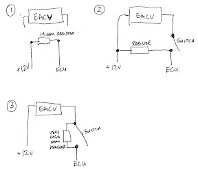
Here are three diagrams to show my ideas. I need feedback as to whether I am on the right track.
Image

Diagram one is just the resistor in the circuit to see if a code is thrown. It not throw a code but resistor got very hot.

Diagram two shows a possible switching circuit that would bypass the EACV when open and when closed run the EACV and the resistor should be bypassed. Am I correct in this logic or does the resistor still stay in play?

Diagram three is another version of two but uses a very high value resistor to basically cut the current off to the EACV when the switch is open. Again, when switch is closed the resistor is bypassed and the EACV operates normally.

Is there a resistor that I could use with a heat sink to keep cool so that I don't burn up some wiring? JS

strudel

#45 โ—ˆ 2026-03-05

Re: COMPETITION

Success :D Look at diagram 2 in my post above and instead of using a single throw switch as shown insert a Single Pole Double Throw (SPDT) ON-ON switch. The resistor is a 10W 10 Ohm.

Cut into BuY wire and add ECU side to Center pin SPDT, add EACV/IACV(BuY) side to one outer SPDT pin and add other outer pin to Resistor. Splice opposite side of resistor to BlY before the EACV/IACV.

This bypasses the EACV and fools the ECU into thinking it is still there. It is either in EACV or bypass mode. NO CEL light when switched over. One could also add in some alert lights if so inclined. JS

Quote:
That's right, and there is a prize too.

Challenge:

Demonstrate a combination of electrical components easily available through major electronics retailers (Radio Shack, Digikey, Arrow, All American, etc.) that when connected to the IACV (Idle Air Control Valve) on an OBD1 ECU fools the ECU into thinking a IACV is actually present. Cheaper = better.


Does this mean I win something?? :mrgreen: This solution is for an OBD0 EACV but in theory should work equally well for an OBD1 IACV as the thing should work identically.