Ltdannear
#1 ◈ 2025-06-29
Thank's to MMuller for this previous post. Re-issued with pics visible:
After many tries and wonders why i could not get datalogging to work, found an error in the directions that comes with the board, if not an error its pretty misleading to noobs like me.
I took a couple of pics of the TTL to RS232 board, with the correct 4 pin connector pin out.
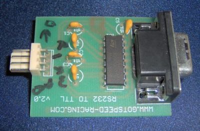
this is the board that im using
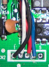
this is how your CN2 should look like after soldering. Directions and pin outs can be found in the wiki;
http://www.pgmfi.org/twiki/bin/view/Library/OBD1CN2
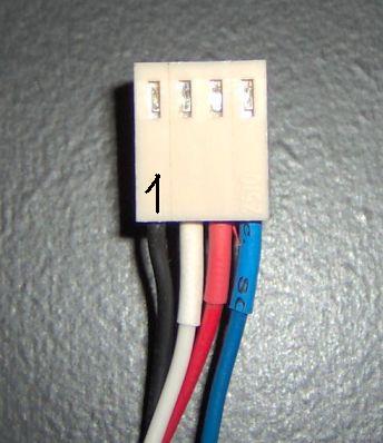
This is how your 4 pin connector to the TTL to RS board should look like.
On the directions with the board, notice that the pin numbers are reversed and shows pin #1 to be TX and #4 to be ground; the picture is also misleading.
going by #1 on the 4 pin connector is should be:
#1=GND(black)
#2=RX(white)
#3=+5(red)
#4=TX(blue)
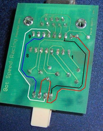
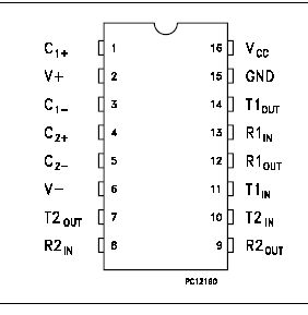
traces on the board and pin outs for the ST232A chip if anybody cares.
Hook everything up, place the board and be done.
Smile
After many tries and wonders why i could not get datalogging to work, found an error in the directions that comes with the board, if not an error its pretty misleading to noobs like me.
I took a couple of pics of the TTL to RS232 board, with the correct 4 pin connector pin out.
this is the board that im using
this is how your CN2 should look like after soldering. Directions and pin outs can be found in the wiki;
http://www.pgmfi.org/twiki/bin/view/Library/OBD1CN2
This is how your 4 pin connector to the TTL to RS board should look like.
On the directions with the board, notice that the pin numbers are reversed and shows pin #1 to be TX and #4 to be ground; the picture is also misleading.
going by #1 on the 4 pin connector is should be:
#1=GND(black)
#2=RX(white)
#3=+5(red)
#4=TX(blue)
traces on the board and pin outs for the ST232A chip if anybody cares.
Hook everything up, place the board and be done.
Smile


