Honda ECU Hardware Architecture
An overview of Honda ECU hardware architecture, including PCB families, MCU specifications, and common hardware modification techniques.
Honda ECU hardware is modular, with specific "families" of ECUs sharing common PCB designs populated with varying components to support different engine configurations. Understanding these hardware commonalities is essential for ECU modification and tuning.
ECU Families
Honda utilized standardized PCB designs across multiple engine platforms. The following categories represent the primary hardware families:
- OBD0 Vacuum Advance: Found in pre-1988 vehicles lacking electronic advance distributors.
- OBD0 DPFI: 1988â1991 dual-point injection units.
- OBD0 MPFI (Non-VTEC): Standard 1988â1991 multi-point injection units.
- OBD0 VTEC: High-performance units such as the PW0 and PR3.
- OBD1 Civic/Integra: Standardized architecture for 1992â1995 platforms.
- OBD1 Prelude/Accord: Distinct hardware architecture for larger displacement platforms.
- V6 ECUs: Shared features across Acura, Rover, Honda Legend, NSX, and V6 Accord platforms.
- OBD2A/OBD2B: Iterative updates to the standard ECU architecture.
- OBD2 K-Series: An evolution of the OBD2B architecture specifically designed for K-series engine management.
Technical Components
Microcontroller Units (MCU)
Most Honda ECUs utilize the Oki 66K series MCU. Many of these units feature internal, copy-protected programs. Specialized MCU readers are required to bypass this protection for diagnostic or reverse-engineering purposes.
EEPROM Modification
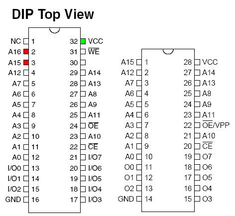
It is possible to expand ECU memory capacity to support multiple programs (multi-mapping). By utilizing an oversized EEPROM, you can toggle between programs by adding a pull-up resistor to the extra address lines (e.g., A15, A16) and using a debounced switch to ground the lines.
Important
When performing memory expansion, ensure the switch is properly debounced to prevent erratic address line behavior, which can cause the ECU to crash or enter an undefined state.
EEPROM Pinout Reference
The following diagram illustrates the pinout configuration for 28-pin and 32-pin EEPROM chips commonly used in ECU modifications.
Hardware Resources
For further technical specifications regarding ECU internals, refer to the following resources:
- 66k Assembler Docs: Technical documentation for the Oki 66K MCU instruction set.
- Rom Maps: Detailed memory mapping for specific ECU firmware versions.