OBD1 Prelude P14 ECU Guide
Hardware specifications, board layout differences, knock sensor configurations, and ROM files for the 1993–1995 OBD1 Prelude P14 ECU.
The P14 ECU was used by Honda in the 1993â1995 OBD1 Prelude Si (USDM H23A1 DOHC non-VTEC engine). It is a robust platform, though there are several distinct internal board revisions that must be identified when socketing or modifying the board.
1. Board Variants & Knock Sensor Configurations
The P14 board exists in two primary configurations based on the presence of the factory knock sensor system:
- Knock-Equipped Boards: These revisions populate the knock processing daughterboard slot. The supporting resistor pads at R118, R119, and R101 are populated from the factory.
- Knockless Boards: These boards lack the knock daughterboard. Resistors R118 and R119 are relocated to pads R142 and R143.
Note
If you are modifying a knock-equipped board to bypass the sensor check, refer to the Knock Sensor Removal / Bypass0 guide.
2. Factory External ROM vs. Romless Boards
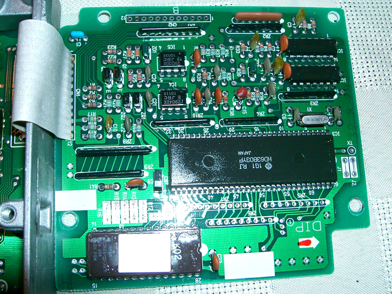
While most USDM OBD1 ECUs require adding a logic latch (74HC373) and jumper (J1) to accept an external ROM, some P14 models (particularly JDM and European knock-equipped revisions) were manufactured with an external ROM from the factory.
Comparing the factory external ROM board with the standard romless board reveals that the external ROM board is missing resistor R15.
3. Board Layout Reference
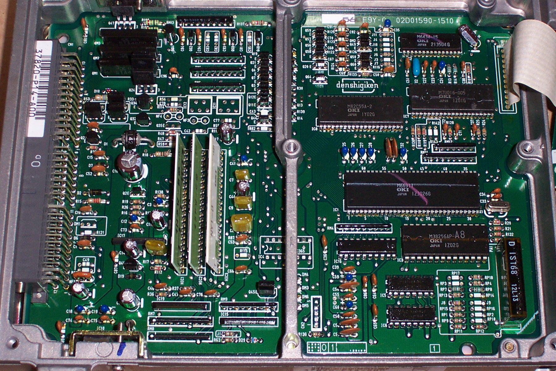
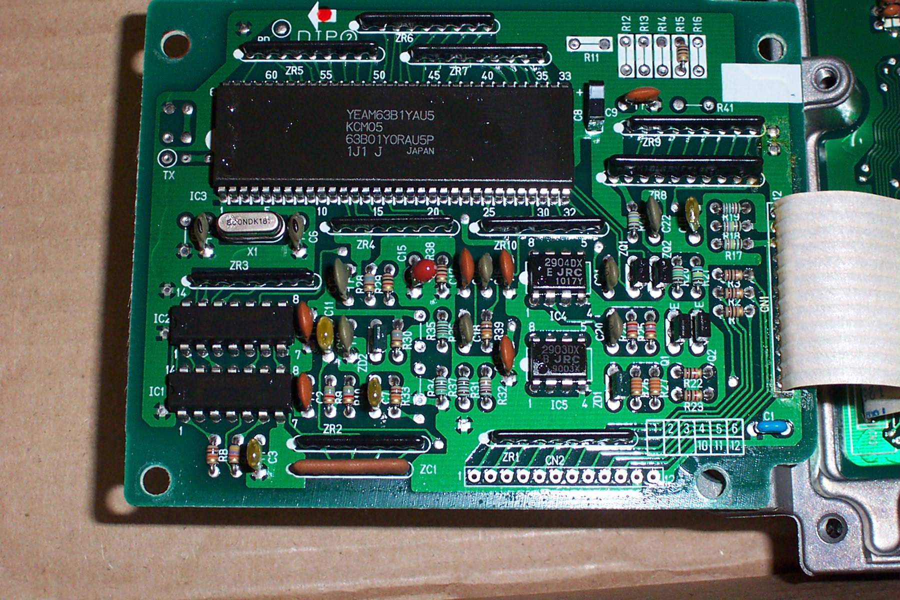
USDM Prelude Si P14-A10 (Manual Transmission)


USDM P14-A00 (4WS and Knock Sensor)
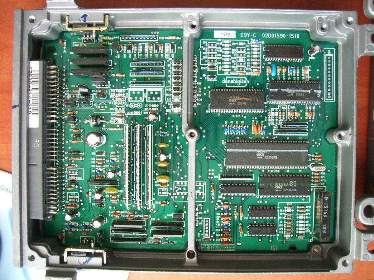
European and Alternate Revisions
4. Archived Files & Downloads
For tuning and analysis, the following stock ROM image was extracted from the factory external ROM version of the P14:
- Download the archived P14 Knock ROM BIN0 (32 KB, Stock H23A calibration)