Honda Data Link Connector (DLC) Reference
Technical reference and location guide for the Honda 3-pin and OBD2 16-pin Data Link Connectors (DLC).
Adapted from pgmfi.org wiki
The Data Link Connector (DLC) is the diagnostic interface port used to communicate with Honda Engine Control Units (ECUs). Depending on the vehicle's model year and On-Board Diagnostics (OBD) generation, Honda utilizes either a proprietary legacy 3-pin connector or the standardized SAE 16-pin J1962 connector.
Proprietary 3-Pin Data Link Connector (OBD0 / OBD1)
On OBD0 and OBD1 vehicles (roughly 1988–1995), Honda used a proprietary 3-pin DLC port to transmit serial K-Line diagnostic data.
- 2-Wire vs. 3-Wire Configuration: Depending on the specific model and trim, this connector may be populated with either two or three wires:
- 3-Wire Models: Provide a constant +12V power supply line, Ground, and a Serial Data line. This allows diagnostic scanners (such as the dealer-level Vetronix Mastertech) to power up directly from the port.
- 2-Wire Models: Only contain the Ground and Serial Data lines. When using a diagnostic tool on these models, the scanner must be plugged into an external 12V power source (such as the cigarette lighter socket or battery clips).
- Service Check Connector (SCS): The 3-pin DLC is always located directly adjacent to a separate 2-pin blue connector. This is the Service Check Connector (SCS) or Service Check Signal port, which is shorted with a jumper or paperclip to read flashing CEL codes on the dashboard.
3-Pin Connector Locations
- Right Lower Edge of Passenger Dash:
- 1994–1995 Accord (L4)
- 1992–1995 Civic
- 1993–1995 Civic del Sol
- Behind Front of Center Console:
- 1992–1995 Honda Prelude (Note: Typically a 2-wire setup requiring external tool power).
- Behind Passenger Glove Box:
- 1995 Honda Odyssey
- Left Driver Kick Panel:
- 1994–1995.5 Honda Passport
3-Pin DLC Hardware Views
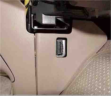
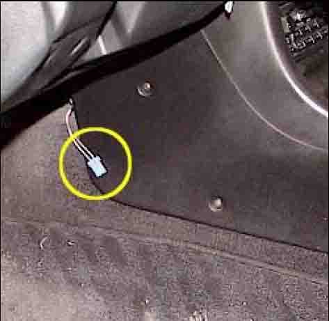 Proprietary 3-pin blue DLC connector (right) and 2-pin blue SCS connector (left) on a 1992–1995 Civic.
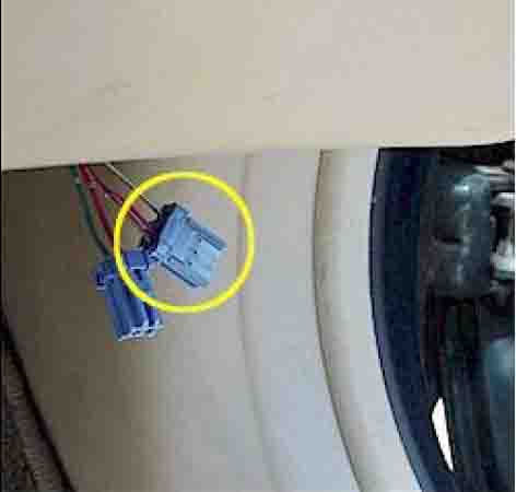 Close-up of the integrated diagnostic port bracket.
Standardized 16-Pin Data Link Connector (OBD2)
Starting with the V6 Accord in 1995, and standard on all USDM vehicles by 1996, Honda adopted the standardized 16-pin OBD2 DLC (SAE J1962).
- Communication Protocol: Honda uses the ISO 9141-2 protocol for OBD2 communications. Pins 7 (K-Line) and 15 (L-Line) are utilized for communication.
- Pin Configuration: Out of the 16 pins, Honda populates up to 7 pins for standard emissions diagnostics. The remaining pins are used for proprietary Honda systems (ABS, SRS, etc.).
16-Pin OBD2 DLC Locations
Because OBD2 standardized the connector but not its exact cockpit placement, Honda utilized several locations depending on chassis architecture:
Location Guide by Model
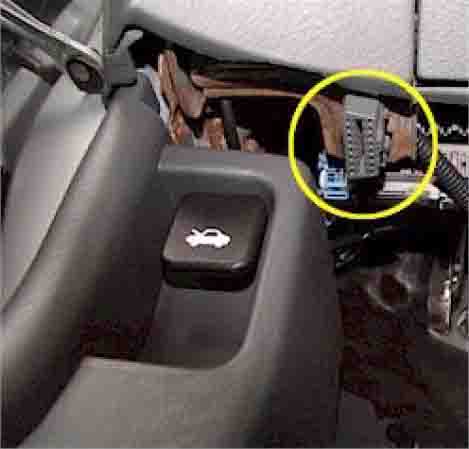
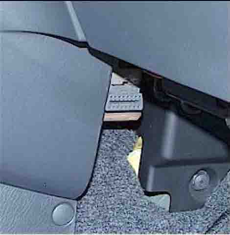
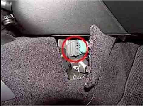
- Under Driver Side Dashboard (Pointing Down):
- 1998–2002 Accord
- 1996–2000 Civic
- 1996–1997 Passport
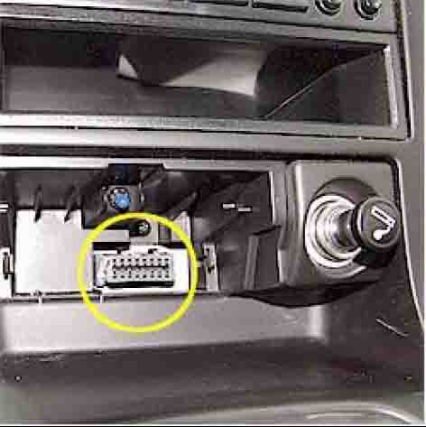
- Behind Center Console Ashtray:
- 1995–1997 Accord V6
- 1996–1997 Accord L4
- Behind Center Console Access Cover:
- 1996–1997 Odyssey
- Behind Front Center Console Trim:
- 1996–1997 Civic del Sol
- 1997–2001 CR-V
- Behind Center Console Removable Accent Panel:
- 1997–2001 Prelude
Credits and source
Authors hondainfo
Source Adapted from DLC on pgmfi.org wiki. Licensed under CC BY-NC-SA 1.0.