OBD1 Honda P28 ECU Reference Guide
A hardware and software reference guide for the USDM and EDM OBD1 P28 SOHC VTEC ECU (from D16Z6 engines), the most popular ECU for custom tuning.
Adapted from pgmfi.org wiki
The P28 Engine Control Unit (ECU) is the most popular OBD1 Honda ECU used for custom socketing and tuning. Sourced originally from 1992–1995 Honda Civic EX/Si and Del Sol models equipped with the SOHC VTEC D16Z6 engine, its hardware is highly versatile and easily adapted to other engine setups.
Overview
Because OBD1 Honda ECUs share a common architecture, the P28 can be easily modified to control non-VTEC or DOHC VTEC engines (like the B16A or B18C) by socketing it and burning custom ROMs. This reference guide details the essential RAM and ROM addresses used in the stock P28 ROM (specifically targeting the standard 304 ROM codebase).
ECU Hardware Scans & Layouts
For hardware modifications, component socketing, or trace repairs, refer to the following circuit board scans:
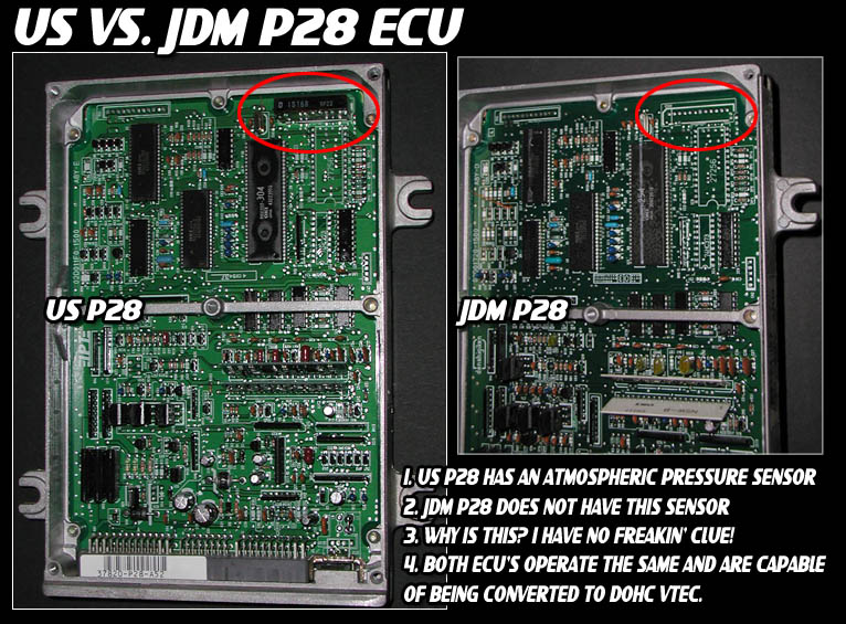
- P28 USDM & JDM Board Comparison
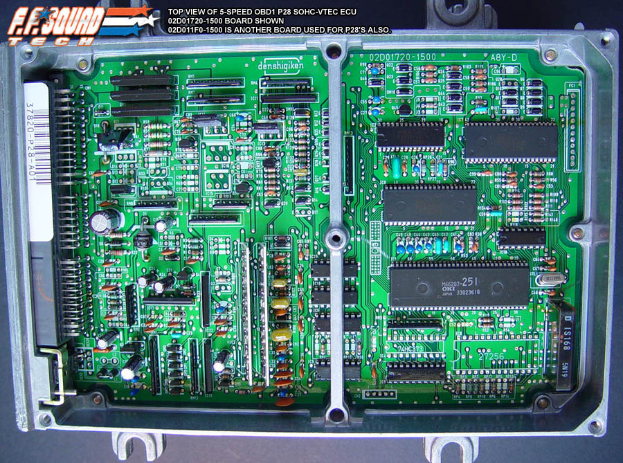
- P28 Manual ECU Board Scan (Top View)
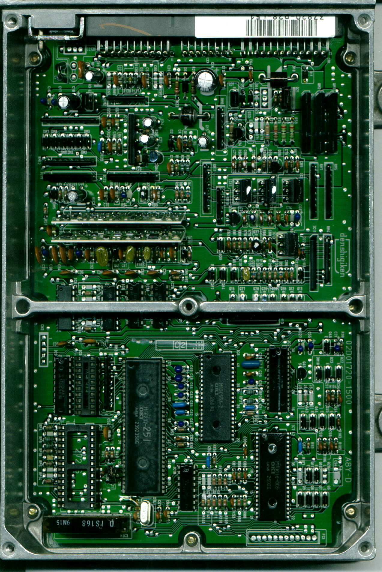
- P28 Automatic ECU Board Scan (Top View)
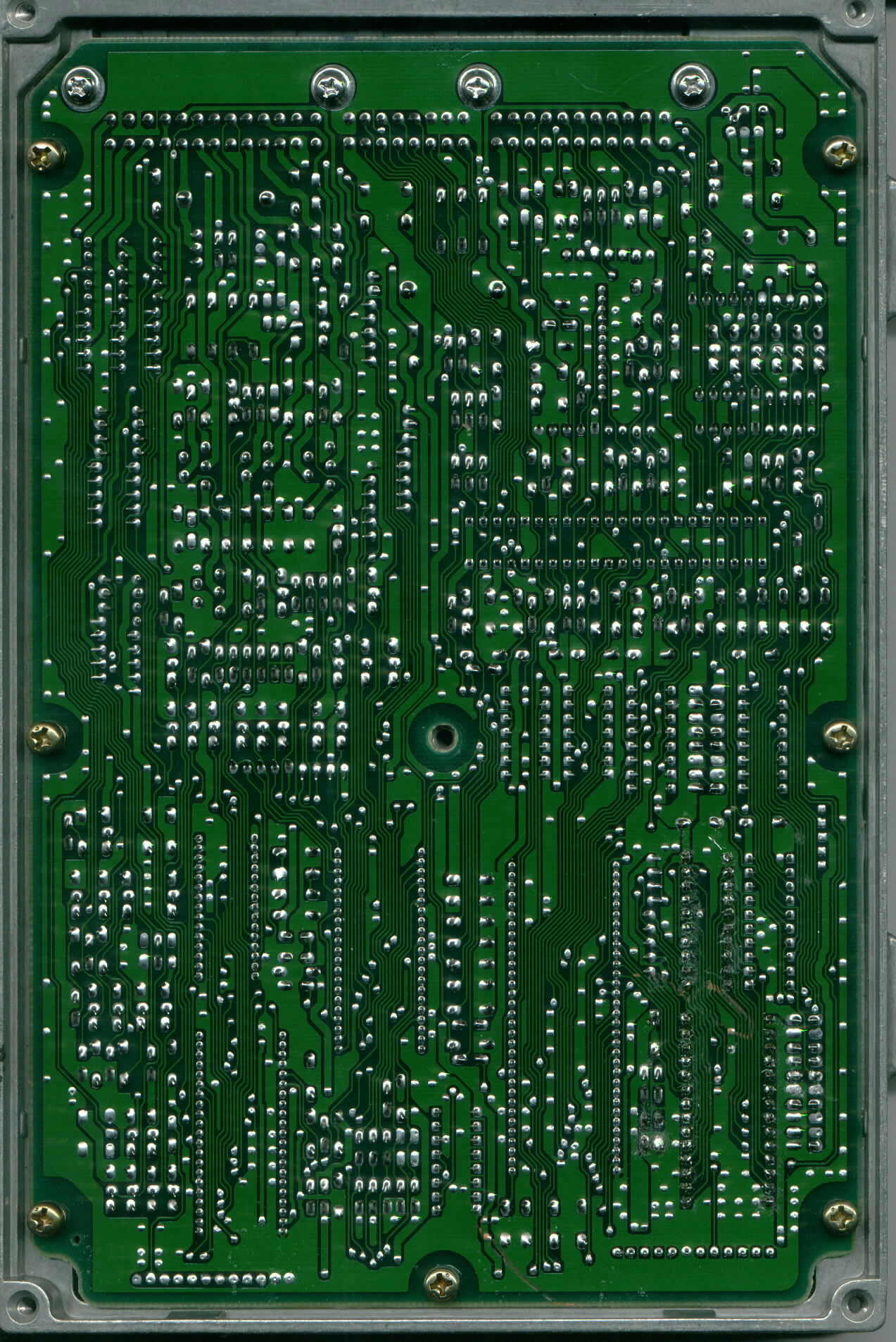
- P28 Automatic ECU Board Scan (Back View)
Note: European market (EDM) P28-G01 ECUs share a circuit board design similar to JDM models. For OBD2-era versions, refer to the P28-G03 ECU (used in 1996–1998 EDM Del Sols).
RAM Address Mapping
Below is the memory map for RAM addresses used during runtime diagnostics and sensor logging:
| Location | Bytes | Description | Notes |
|---|---|---|---|
| 00BB | 1 | MAP Sensor | Manifold Absolute Pressure analog input (0V-5V, scaled 0x00-0xFF) |
| 00C4 | 2 | Current RPM | Engine speed (uses OBD1 16-bit RPM scale) |
| 00CC | 1 | VSS Sensor | Vehicle Speed Sensor value in km/h |
| 00D9 | 1 | ECT Sensor | Engine Coolant Temperature sensor reading |
| 00DA | 1 | O2 Sensor | Oxygen Sensor signal |
| 0210.3 | 1b | Power Steering Pressure (PSP) | PSP switch input. Grounding pin B8 sets this bit to 1 |
| 0216.4 | 1b | VTEC Enable RAM Flag | Active VTEC status bit. Set if ROM address 0x60E6 is not 0x00 |
| 0227.4 | 1b | Knock Enable RAM Flag | Active Knock control status bit. Set if ROM address 0x60E7 is not 0x00 |
ROM Address Mapping
Below are the hex address offsets within the 28-pin EEPROM chip for fuel maps, ignition maps, and software parameters:
| Location | Bytes | Description | Notes |
|---|---|---|---|
| 0652 | 6 | Injector Test Jump Routine #1/2 | Change to 03 5F 06 to disable injector test (both patches must be applied) |
| 1292 | 1 | VTEC Coolant Temp Check | Minimum temp to allow VTEC. 0x44 enables check, 0xFF disables |
| 1580 | 6 | Injector Test Jump Routine #2/2 | Change to 03 9A 15 to disable injector test (both patches must be applied) |
| 238A | 6 | O2 Heater Jump Routine | Change to 03 C5 23 to disable O2 heater sensor check |
| 2BAD | 6 | Checksum Jump Routine | Change to 03 B6 2B to disable checksum check (prevents solid CEL on custom tunes) |
| 445C | 6 | VTEC Solenoid Check Jump | Change to 03 7A 44 to disable VTEC Solenoid error (Error Code 21) |
| 447D | 6 | VTEC Pressure Check Jump | Change to 03 95 44 to disable VTEC Pressure Switch error (Error Code 22) |
| 60E6 | 1 | VTEC Enable | 0xFF enables VTEC functionality, 0x00 disables |
| 60E7 | 1 | Knock Sensor Enable | 0xFF enables knock sensor check, 0x00 disables |
| 60E9 | 1 | Barometric Sensor Enable | 0xFF enables baro sensor check, 0x00 disables |
| 60F2 | 1 | ELD Sensor Enable | Electrical Load Detector. 0xFF enables, 0x00 disables |
| 60FA | 1 | VTEC VSS Check | 0x00 enables VSS check, 0xFF disables. See disabling VTEC VSS check |
| 60FB | 1 | Debug Mode | 0xFF enables debug mode, 0x00 disables |
| 6542 | 1 | VTEC Crossover Point | Base RPM crossover parameter |
| 6543 | 1 | VTEC Crossover Point | Crossover RPM parameter (uses OBD1 8-bit Low Cam RPM formula) |
| 6544 | 1 | VTEC Crossover Point | (Alternative configuration byte) |
| 6545 | 1 | VTEC Crossover Point | (Alternative configuration byte) |
| 6546 | 1 | VTEC Crossover Point | (Alternative configuration byte) |
| 6547 | 1 | VTEC Crossover Point | (Alternative configuration byte) |
| 6548 | 1 | VTEC Crossover Point | (Alternative configuration byte) |
| 6549 | 1 | VTEC Crossover Point | (Alternative configuration byte) |
| 7000 | 10 | Low Cam mBar Scale | Fuel and ignition load scaling index (10 columns) |
| 700A | 10 | High Cam mBar Scale | VTEC load scaling index (10 columns) |
| 7014 | 20 | Low Cam RPM Scale | Low cam RPM scaling index (20 rows) |
| 7028 | 20 | High Cam RPM Scale | VTEC RPM scaling index (20 rows) |
| 7050-7117 | 200 | Low Cam Fuel Table | 10x20 base fueling lookup map |
| 7118-7121 | 10 | Low Cam Fuel Coeff | Low cam multiplier coefficients |
| 7122-71E9 | 200 | High Cam Fuel Table | 10x20 VTEC fueling lookup map |
| 71EA-71F3 | 10 | High Cam Fuel Coeff | High cam multiplier coefficients |
| 72E4-73AB | 200 | Low Cam Timing Table | 10x20 low cam ignition advance map |
| 73AC-7473 | 200 | High Cam Timing Table | 10x20 VTEC ignition advance map |
| 7550-7617 | 200 | Low Cam Target Lambda Table | Closed-loop target air-fuel ratio lookup table |
| 7618-76DF | 200 | High Cam Target Lambda Table | Closed-loop target air-fuel ratio lookup table |
Credits and source
Authors tungsten2k, blundar, dohcvtec, tom667, peluca, -anton-
Source Adapted from P28 on pgmfi.org wiki. Licensed under CC BY-NC-SA 1.0.