OBD1 Honda P72 ECU Reference Guide
A comprehensive hardware and software reference guide for the OBD1 P72 Integra GS-R DOHC VTEC ECU, including RAM and ROM mapping.
Adapted from pgmfi.org wiki
The P72 Engine Control Unit (ECU) is a highly versatile OBD1 Honda ECU. Originally equipped in 1994–1995 Acura Integra GS-R models with the DOHC VTEC B18C1 engine, it is unique among Honda ECUs for containing built-in circuitry to control both secondary intake manifold runners (IAB) and a knock sensor from the factory.
Overview
Because the P72 has native hardware components to drive Intake Air Bypass (IAB) solenoids and knock sensor diagnostics, it is often used as the hardware platform for high-performance builds utilizing dual-stage intake manifolds (like the stock GS-R manifold) or custom knock control maps.
This reference guide details the essential RAM (runtime logging) and ROM (EEPROM calibration) memory address locations for the OBD1 P72 ECU (focusing on the stock USDM 273 and JDM 203 code bases).
ECU Hardware Scans & Layouts
For circuit repairs, trace socketing, or component validation, refer to the following top-view board scan:
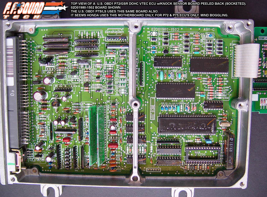
Note: This guide focuses specifically on the 1994–1995 OBD1 P72 ECU. While 1996–2000 Integra GS-Rs also utilize P72 ECUs, those are OBD2 units and feature different circuit boards and internal memory architecture.
RAM Address Mapping
Below is the memory map of active RAM addresses used for diagnostics, data logging, and sensor feedback:
| Location | Bytes | Description | Notes |
|---|---|---|---|
| 00BB | 1 | Raw MAP Sensor | Manifold Absolute Pressure raw analog input (scaled 0x00-0xFF) |
| 00BF | 1 | Adjusted MAP | Calibrated manifold absolute pressure value used for load lookup |
| 00C3 | 1 | Current RPM (8-bit) | Secondary 8-bit RPM representation (copied to 0x236) |
| 00C4 | 2 | Current RPM | Diagnostic engine speed (OBD1 16-bit RPM value) |
| 00CC | 1 | VSS Sensor | Vehicle Speed Sensor value in km/h |
| 00D1 | 1 | Current TPS | Throttle Position Sensor analog input (see TPS Sensor Calibration) |
| 00D4 | 1 | Raw TP Sensor | Unscaled Throttle Position Sensor reading |
| 00D5 | 1 | TPS Delta | Rate of throttle position change (used for acceleration fuel enrichment) |
| 00D8 | 1 | IAT Sensor | Intake Air Temperature sensor reading |
| 00D9 | 1 | ECT Sensor | Engine Coolant Temperature sensor reading |
| 00DA | 1 | O2 Sensor | Narrowband Oxygen Sensor feedback signal |
| 011A | 1 | CEL Diagnostics Byte 1 | Active diagnostic trouble code register 1 |
| 011B | 1 | CEL Diagnostics Byte 2 | Active diagnostic trouble code register 2 |
| 011E.3 | 1b | Transmission Jumper | Hardware config jumper. 1 = Automatic, 0 = Manual transmission |
| 0127.1 | 1b | VTEC Status Bit | 1 if VTEC solenoid output is active, 0 otherwise |
| 0131.0 | 1b | VTEC VSS Check Status | Set to 1 if speed > 15 km/h, cleared to 0 if speed < 10 km/h |
| 0131.1 | 1b | VTEC RPM Check Status | Set to 1 if engine RPM exceeds crossover point (includes hysteresis) |
| 0192 | 2 | Rev Limit Cut | Engine speed fuel-cut limit |
| 0194 | 2 | Rev Limit Resume | Engine speed fuel-cut recovery point |
| 01D2 | 1 | Active Map Column | Column pointer for fuel/ignition load scaling |
| 01D8 | 1 | Low Cam Active Row | Low cam RPM row pointer |
| 01D9 | 1 | High Cam Active Row | High cam RPM row pointer |
| 0210.3 | 1b | PSP Switch Input | Power Steering Pressure switch status. 0 if grounded (active), 1 otherwise |
| 0216.4 | 1b | VTEC Enable RAM Flag | General VTEC system status bit |
| 0216.6 | 1b | O2 Heater Enable Flag | Oxygen Sensor heater relay control status bit |
| 0227.4 | 1b | PA Sensor Enable Flag | Barometric Pressure sensor diagnostic status |
| 0227.6 | 1b | Knock Sensor Enable Flag | Knock sensor diagnostic status |
| 0236 | 1 | 8-bit RPM (IAB Control) | Engine speed value used for IAB secondary runner control lookup |
| 0244 | 1 | Knock Retard | Degree offset of ignition timing pulled due to active knock detection |
| 0246 | 1 | Ignition Advance | Final calculated ignition timing advance in degrees BTDC |
| 025A | 2 | Target Idle RPM | Current target idle speed based on coolant temp (ECT) |
| 03A0 | 2 | Injector Duration | Final calculated injector pulse-width |
| 03CD | 1 | Baro Sensor | Barometric Atmospheric pressure sensor value |
| 03D2 | 1 | ELD Input | Electrical Load Detector analog reading |
| P0.0 | 1b | A/C Clutch Relay | Pin control for A/C compressor clutch |
| P0.1 | 1b | Purge Solenoid Relay | Pin control for EVAP canister purge solenoid |
| P0.5 | 1b | IAB Output | Pin control for secondary intake manifold runners (solenoid active low) |
| P1.0 | 1b | VTEC Left Output | Left transistor pin control for VTEC solenoid relay (IC14) |
| P1.1 | 1b | VTEC Right Output | Right transistor pin control for VTEC solenoid relay (IC13) |
ROM Address Mapping
Below are the hex address offsets within the 28-pin EEPROM chip for the standard P72 USDM 273 codebase:
| Location | Bytes | Description | Notes |
|---|---|---|---|
| 0630 | 3 | Injector Test Bypass #1 | Change to 03 3D 06 to bypass injector diagnostic check |
| 0B85 | 2 | Low Cam Ignition Columns | Count of load columns in the low cam ignition map |
| 0B87 | 2 | Low Cam Ignition Rows | Count of RPM rows in the low cam ignition map |
| 11BA | 1 | VTEC On/Off Hysteresis | Crossover logic control parameter |
| 120E | 1 | VTEC Coolant Temp Check | Minimum temp to engage VTEC. 0x44 enables check, 0xFF disables |
| 1520 | 3 | Injector Test Bypass #2 | Change to 03 3A 15 to bypass secondary injector diagnostics |
| 2315 | 3 | O2 Heater Check Bypass | Change to 03 50 23 to disable O2 heater sensor diagnostic checks |
| 2D43 | 2 | Rolling Target Idle RPM | Target idle speed formula: RPM = 1,875,000 / (word at 0x2D43) |
| 2D58 | 2 | Cold Target Idle RPM | Target idle speed formula: RPM = 1,875,000 / (word at 0x2D58) |
| 2D81 | 2 | Warm Target Idle RPM | Target idle speed formula: RPM = 1,875,000 / (word at 0x2D81) |
| 3BE1 | 3 | VTP Sensor Disable | Change to 03 FF 3B to disable VTEC Pressure Switch checks |
| 43A2 | 1 | IAB Open Threshold | Engine speed where secondary runners open (8-bit RPM value) |
| 439D | 1 | IAB Close Threshold | Engine speed where secondary runners close (8-bit RPM value) |
| 5466 | 1 | VTEC System Enable | 0xFF enables VTEC functionality, 0x00 disables |
| 5467 | 1 | Knock Sensor Enable | 0xFF enables knock diagnostics, 0x00 disables |
| 5468 | 1 | O2 Heater Sensor Enable | 0xFF enables O2 heater diagnostics, 0x00 disables |
| 5469 | 1 | PA Sensor Enable | 0xFF enables baro sensor diagnostics, 0x00 disables |
| 547D | 1 | VTEC VSS Check | 0x00 enables minimum speed check, 0xFF disables check |
| 547E | 1 | Debug Mode | 0xFF enables debug mode diagnostics, 0x00 disables |
| 5489 | 1 | IAB System Enable | 0xFF enables IAB solenoid control logic, 0x00 disables |
| 58DA | 1 | Rev Resume Point #1 | Engine speed where fuel cut recovers (primary) |
| 58E0 | 1 | Rev Cut Point #1 | Engine speed limit fuel cut (primary) |
| 58E6 | 1 | Rev Resume Point #2 | Engine speed where fuel cut recovers (secondary) |
| 58EC | 1 | Rev Cut Point #2 | Engine speed limit fuel cut (secondary) |
| 7C4A | 10 | Fuel MAP Load Scaler | MAP sensor pressure scaling index for fuel tables |
| 7C54 | 10 | Ignition MAP Load Scaler | MAP sensor pressure scaling index for ignition tables |
| 7C68 | 20 | Low Cam RPM Scaler | Low cam RPM scaling index (20 rows) |
| 7C7C | 15 | High Cam RPM Scaler | VTEC RPM scaling index (15 rows) |
| 7C9A | 200 | Low Cam Fuel Table | 10x20 base fueling lookup map |
| 7D6C | 150 | High Cam Fuel Table | 10x15 VTEC fueling lookup map |
| 7E0C | 200 | Low Cam Ignition Map | 10x20 low cam ignition advance map |
| 7ED4 | 150 | High Cam Ignition Map | 10x15 VTEC ignition advance map |
| 7F6A | 200 | Closed-Loop Target Lambda | Closed-loop target air-fuel ratio lookup table |
Credits and source
Authors tungsten2k, blundar, flyrod, dohcvtec, mind-eracer, mr2mkii, 91crxsi
Source Adapted from P72 on pgmfi.org wiki. Licensed under CC BY-NC-SA 1.0.