Oxygen (O2) Sensor Technical Reference
Technical guide on Honda narrowband and wideband oxygen sensors, including operating principles, output characteristics, and 1-wire to 4-wire conversion wiring.
The Oxygen (O2) sensor measures the oxygen content of exhaust gases. The ECU uses this data to determine if the engine is running rich or lean, adjusting fuel delivery in closed-loop mode to maintain a stoichiometric balance.
Sensor Types
Honda has utilized several styles of oxygen sensors across different generations:
- 1-Wire Sensor (OBD0 / Early OBD1): An unheated narrowband sensor. It relies entirely on exhaust heat to reach its operating temperature (approximately 315°C / 600°F).
- 4-Wire Sensor (OBD1 / OBD2): Features an internal heating element powered by the vehicle's electrical system, allowing the sensor to reach operating temperature quickly and maintain stability at idle or light loads.
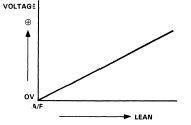
- 5-Wire Wideband Sensor (L1H1 / LAF): Used on specific lean-burn engines (e.g., 1992â1995 Civic VX, 1996â1998 Civic HX). Unlike narrowband sensors, these measure air-fuel ratios (AFR) across a wide range.
Narrowband Output Characteristics
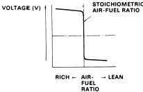
Standard 1-wire and 4-wire sensors are narrowband (lambda) sensors designed to detect a specific ratio: stoichiometric (14.7:1 air-fuel ratio).
- Stoichiometric (14.7:1): Outputs approximately 0.45V.
- Rich (AFR < 14.7): Output swings high (up to ~0.9Vâ1.0V).
- Lean (AFR > 14.7): Output swings low (down to ~0.1V).
Note
Because the voltage output curve is extremely steep around the 14.7:1 mark, the sensor acts as a binary switch. The ECU cannot determine the magnitude of the rich or lean condition; it only identifies which side of stoichiometry the engine is currently operating on.
Output Curves
Wiring Reference
Converting 1-Wire to 4-Wire O2 Sensor
When performing an OBD1 swap on an older chassis (e.g., EF Civic or DA Integra), a 4-wire heated O2 sensor must be integrated with the OBD1 ECU (e.g., P28, P30) to prevent Heater Circuit trouble codes (Code 41).
| O2 Sensor Wire | Function | Connection Point |
|---|---|---|
| White | Signal | ECU Pin D14 (O2 Signal) |
| Green | Sensor Ground | ECU Pin D22 (SG2 / Sensor Ground) |
| Black (Heater) | +12V Power | Switched 12V source (e.g., Yellow/Black wire at distributor) |
| Black (Heater) | Heater Control | ECU Pin A6 (Heater Ground Control) |
Important
Ensure the heater ground control wire is connected to the ECU pin A6. Failure to provide a switched ground will result in a permanent heater circuit fault code.