OBD1 Honda P13 ECU Reference Guide
A comprehensive technical reference for the OBD1 P13 Prelude H22A ECU, detailing RAM/ROM memory maps, diagnostic registers, and hardware modification procedures.
The P13 Engine Control Unit (ECU) is the factory controller for the 1993â1995 OBD1 Honda Prelude VTEC equipped with the 2.2L DOHC VTEC H22A engine.
Overview
Unlike standard OBD1 Civic/Integra ECUs, the P13 utilizes a unique circuit board architecture and a non-standard fuel and ignition map structure (1x40 RPM axis scaling). This guide provides the essential RAM and ROM memory address locations required for custom tuning, datalogging, and hardware modification.
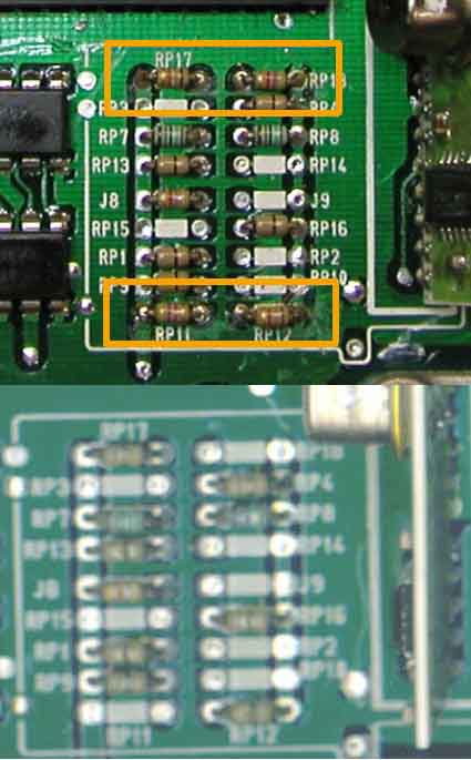
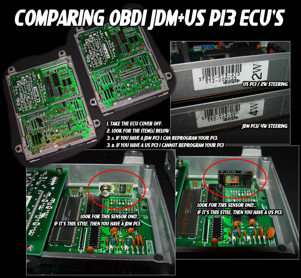
Board Identification & Variations
Circuit board layouts differ significantly between JDM and USDM models:
RAM Address Mapping
The following memory addresses are used for runtime diagnostic monitoring and datalogging:
| Location | Bytes | Description | Notes |
|---|---|---|---|
| 00A4 | 1 | MAP Sensor | Raw analog voltage (0V-5V) |
| 00AB | 1 | TPS Sensor | Scaled input (0x00-0xFF) |
| 00AE | 2 | Current RPM | 16-bit RPM value |
| 00D9 | 1 | ECT Sensor | Engine Coolant Temperature |
| 00DF | 1 | VSS Sensor | Speed in km/h |
| 00ED | 1 | Active MAP Column | Load pressure pointer |
| 00EE | 1 | Low Cam Active Row | Low cam RPM pointer |
| 00EF | 1 | High Cam Active Row | VTEC RPM pointer |
| 0110-0114 | 2 ea | CEL Diagnostics | Active fault code registers |
| 016A | 2 | Rev Limit Cut | 16-bit fuel cut RPM |
| 016C | 2 | Rev Limit Resume | Fuel cut recovery point |
| 021D.1 | 1b | VTEC Status Flag | 1 = Active, 0 = Inactive |
| 0224.0 | 1b | A/C Switch Input | 1 = Active (Pin B5) |
| 03D0 | 1 | O2 Sensor | Narrowband feedback |
| 03D2 | 1 | IAT Sensor | Intake Air Temp |
| 03D3 | 1 | Baro Sensor | Barometric pressure |
ROM Address Mapping
These hex address offsets apply to the 28-pin EEPROM for stock P13 calibrations:
| Location | Bytes | Description | Notes |
|---|---|---|---|
| 0C21 | 2 | High Cam Rev Resume | VTEC fuel cut recovery |
| 0C26 | 2 | High Cam Rev Limit | VTEC fuel cut |
| 0D22 | 4 | Checksum Jump | See Disabling Checksum |
| 2EAC | 1 | Speed Limiter | Set to 0xFF to disable |
| 35CA | 1 | VTEC ECT Check | 0x44 = Enabled, 0xFF = Disabled |
| 5403 | 2 | Low Cam Rev Resume | Low cam recovery |
| 5407 | 2 | Low Cam Rev Limit | Low cam fuel cut |
| 6000 | 40 | Low Cam RPM Scaler | 1x40 row index |
| 6028 | 40 | High Cam RPM Scaler | 1x40 row index |
| 60AA | 200 | Low Cam Fuel Table | 10x20 map |
| 6172 | 200 | High Cam Fuel Table | 10x20 map |
| 63F8 | 200 | Low Cam Ignition | 10x20 map |
| 659C | 200 | High Cam Ignition | 10x20 map |
Advanced Tuning Calibration
Disabling Checksum
Important
Modifying ROM bytes will trigger a Check Engine Light (CEL) due to a checksum mismatch.
To disable the checksum routine:
- Navigate to hex address
0x0D22. - Replace the bytes
90 9D F1 7Fwith03 36 0D 00.
Datalogging Registers
- Serial Receive Buffer (SRBUF):
0x07D - Serial Transmit Buffer (STBUF):
0x07C - Interrupt Vector: Starts at
0x0043. Custom routines should be placed at0x00DB.
Hardware Modifications
Auto to Manual Transmission Conversion
JDM Automatic P13 ECUs can be converted to manual specifications by modifying the resistor jumpers:
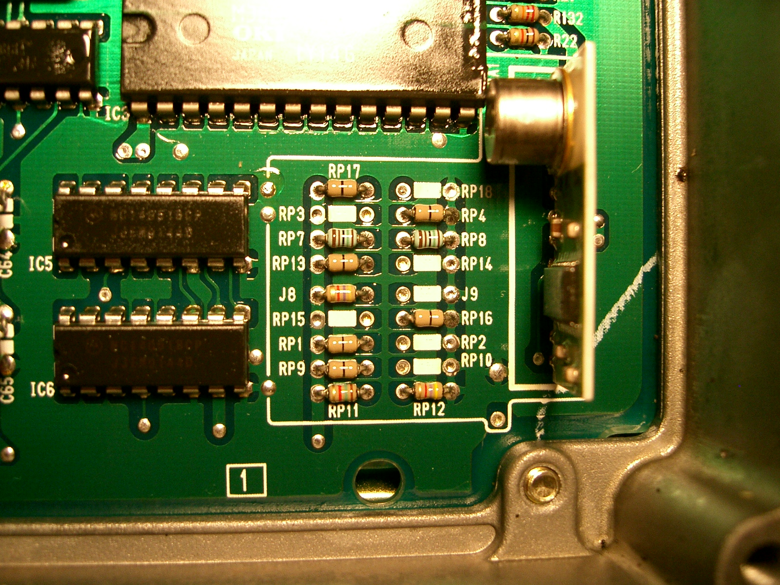 Relocate jumpers on RP11 and RP12 to toggle between automatic and manual configurations.
Knock Sensor Bypass
Note
If swapping an H22A into a chassis without a knock sensor, you must bypass the sensor check to avoid Error Code 23. Refer to the Knock Sensor bypass guide0.