Logging an External 0-5 V Sensor via P30 D12
Technical guide for utilizing the undocumented D12 analog input on USDM OBD1 P30 ECUs for 0-5 V external sensor logging.
This guide details the implementation of the undocumented D12 analog input on USDM OBD1 P30 ECUs to record external 0-5 V signals, such as EGT amplifier or wideband O2 controller outputs.
Warning
This procedure is documented specifically for the USDM P30. While other USDM OBD1 ECUs may share similar circuitry, compatibility is not guaranteed. JDM P30 ECUs utilize a different circuit configuration and require specific modifications.
D12 Analog Input Architecture
On the USDM P30, the D12 pin routes to the 66207 microcontroller's AI3 input at Pin 57.
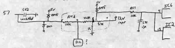 Archived schematic of the USDM P30 analog-input section.
ADC Data Specifications
| Item | Specification |
|---|---|
| Input Range | 0â5 V at D12 |
| Main Logged Byte | RAM 0067h |
| Main-Byte Scale | ~0.02 V per count (00h = 0 V, 0FFh = 5 V) |
| Additional ADC Bits | RAM 0066h (contains the two LSBs of the 10-bit ADC result) |
| Signal Loss | ~1% from D12 to AI3 at 66207 Pin 57 |
Optional C42 Filter Installation
Stock USDM P30 ECUs typically lack a component at the C42 position. To improve signal stability, a 1 uF, 35 V tantalum capacitor may be installed.
Caution
Verify capacitor polarity and board layout against your specific ECU revision before installation. The positive terminal should face away from the
66207microcontroller, matching the orientation of adjacent capacitors.
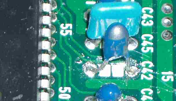 Board view showing the C42 capacitor installation.
JDM P30 Considerations
The JDM P30 architecture differs from the USDM variant:
- Grounding: The USDM P30 grounds AI5, whereas the JDM P30 grounds AI3.
- Routing: On JDM units, D12 is routed to AI5 at
66207Pin 63. - Modification: The JDM D12 path contains uninstalled components that must be populated before the input can be utilized.
Refer to the JDM P30 D12 modification guide0 for specific circuit requirements and software considerations regarding AI5.
Implementation Use Cases
The D12 input can be configured for various data acquisition tasks:
- EGT Logging: Interfacing with thermocouple amplifiers providing a 0-5 V output.
- Wideband O2 Logging: Recording wideband data while maintaining the factory narrowband O2 sensor functionality.
- Switch Input: Utilizing the pin as a software-interpreted switch input (requires an external pull-up resistor).
Important
Using D12 as a switch input precludes its use for simultaneous analog sensor logging.