P30 D12 Analog Input for External 0–5 V Sensor Datalogging
Archived method for USDM P30 D12 analog input to datalog external 0-5 V sensors on OBD1 ECUs.
The undocumented D12 analog input on USDM OBD1 P30 ECUs can be used to datalog external 0â5 V signals, such as exhaust gas temperature (EGT) amplifier outputs or wideband oxygen sensor controllers. This method is archived and based on direct testing on a single USDM P30 variant.
Warning
Compatibility testing was performed only on a USDM P30. While other USDM OBD1 ECUs are suspected to share this circuit and JDM P30 ECUs appear similar in structure, confirmed compatibility data is unavailable. JDM P30 variants use a different and incomplete D12 circuit.
D12 Analog Input Architecture
On the documented USDM P30, D12 connects to ADC input AI3 on Pin 57 of the 66207 integrated circuit. The archived schematic documents the analog input stage around this connection.
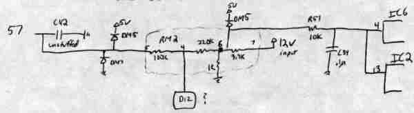 Archived schematic of the P30 USDM analog input stage.
The archived documentation describes the recorded data characteristics as follows:
| Parameter | Specification |
|---|---|
| Input Range | 0â5 V applied to D12 |
| Primary Datalog Byte | RAM address 0067h |
| Primary Byte Scale | Approximately 0.02 V per count; 00h = 0 V, 0FFh = 5 V |
| Additional ADC Bits | RAM address 0066h contains the two least significant bits of the 10-bit ADC result |
| Signal Loss | Approximately 1% attenuation from D12 to AI3 at Pin 57 of 66207 |
The original author determined the two additional ADC bits unnecessary for EGT datalogging and did not provide calibration or detailed loss measurement methodology.
Optional C42 Filter Capacitor
The original documented USDM ECU had no component installed at C42. The archived recommendation was to install a 1 µF, 35 V tantalum capacitor to smooth the ADC input, with positive polarity oriented away from the 66207 and aligned with surrounding capacitors in that row.
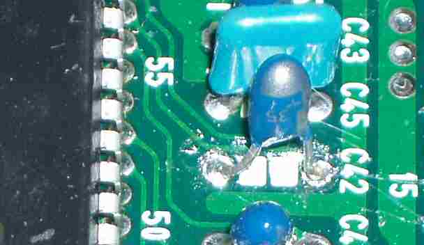 Archived photograph showing installed
 C42 filter capacitor.
Caution
Verify capacitor polarity and board schematic against your actual ECU hardware. This recommendation was not documented across all P30 board revisions or other ECU variants and installation without verification may cause damage.
JDM P30 Circuit Differences
The archived documentation notes that the USDM P30 ties AI5 to ground, whereas the JDM P30 ties AI3 to ground and routes D12 to AI5 on Pin 63 of the 66207. The JDM D12 path also includes unpopulated components and requires circuit modification before use as described for USDM variants.
Refer to JDM P30 D12 Modification0 for required circuit alterations and associated unresolved AI5 software warnings.
Archived Application Scenarios
The archived documentation discusses the following potential uses for D12:
- EGT Datalogging â Capture thermocouple amplifier output (0â5 V range).
- Wideband O2 Datalogging â Log wideband oxygen sensor data while preserving the original narrowband input.
- Software-Interpreted Switch Input â Implement digital input via pull-up resistor (proof-of-concept only; consumes D12 and prevents simultaneous sensor datalogging).
The switch input concept was presented as a programming exercise in the source material and is not recommended for concurrent sensor datalogging.