5050s
Use this method if you install a 5050s in IC14 and you get a MIL code 21. STEP 1 modify and install the VTEC parts as normal but stop at the installation...
Adapted from pgmfi.org wiki
Use this method if you install a 5050s in IC14 and you get a MIL code 21. STEP 1 modify and install the VTEC parts as normal but stop at the installation of IC14 STEP 2 install the 5050s in the IC14 position and do not solder pin 4 of the 5050s 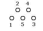 STEP 3 on the PCB of the ECU bridge pads 2 and 4 ( do not bridge the legs of the 5050s )
 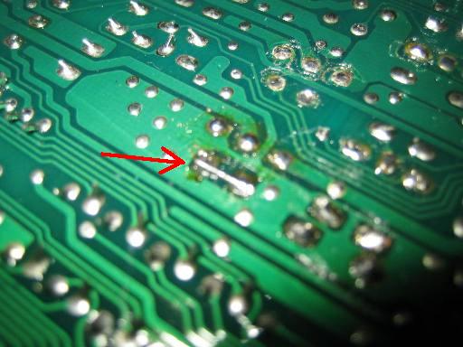 STEP 4 get a 820R resistor and solder 4cm of wire to one side and solder the other end of the resistor to the emitter of
 Q102 ( as a 5v ref ) STEP 5 solder the other side of the wire to pin 4 of the 5050s, you might want to trim back the leg a bit so it doesn't stick out to much. 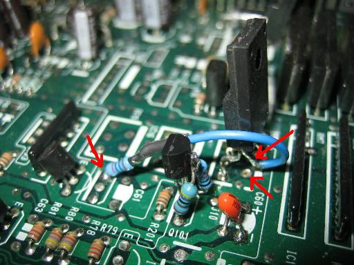 and thats it, enjoy your VTEC I tested a ECU with this method on the Engine Simulator in VTEC for over 5 minuits continuously and it did not mis a beat and nothing got to hot. link to thread https://web.archive.org/web/http://forum.pgmfi.org/viewtopic.php?t=12672cheers John b16A2
| Attachment: | Modify: | Size: | Date: | Who: | Comment: |
|---|---|---|---|---|---|
 5050s-VTEC007.jpg 5050s-VTEC007.jpg |
mod | 37420 | 27 Jan 2007 - 14:30 | b16a2 | link pin 2 and 4 |
| 5050s-VTEC006.jpg |
mod | 46044 | 27 Jan 2007 - 14:31 | b16a2 | final layout |
| image003.jpg |
mod | 2848 | 27 Jan 2007 - 14:32 | b16a2 | 5050s layout |
Credits and source
Authors b16a2
Source Adapted from 5050s on pgmfi.org wiki. Licensed under CC BY-NC-SA 1.0.