Honda ECU Serial Datalogging (`CN2` TTL Header)
Learn how Honda OBD1 ECUs communicate with tuning laptops via serial TTL signals (CN2 header), including pinouts, settings, and wiring warnings.
Adapted from pgmfi.org wiki
Serial communication is the primary mechanism used to transmit runtime diagnostics (sensor readings, engine speed, and error codes) from a Honda ECU to a laptop running tuning software (such as Crome, Hondata, or Neptune).
On OBD1 Honda ECUs (like the P28 or P30), this communication is handled through a physical 4-pin or 5-pin male pin header designated as CN2, located on the right side of the main circuit board.
1. Critical Voltage Warning: TTL vs. RS-232
Caution: The Honda ECU serial port uses TTL (Transistor-Transistor Logic) levels. TTL signals operate strictly at low voltages: 0V (logic low) and 5V (logic high).
Standard computer serial ports and cheap DB9 cables use RS-232 voltage levels, which range from -12V (logic low) to +12V (logic high). Connecting a standard RS-232 cable directly to the ECU's CN2 header will immediately destroy the ECU's internal OKI microcontroller.
Always use a dedicated TTL-to-USB converter interface (such as a Moates Extreme OBD1 cable or a standard FTDI/CP2102 USB-to-TTL board) to bridge the connection.
2. CN2 Header Pinout
On USDM OBD1 motherboards, the CN2 port consists of 5 pins. However, only 4 pins are used for serial datalogging. Note that Pin 1 is typically marked on the board by a square solder pad or a small number "1" print:
| Pin Number | Signal Name | Description |
|---|---|---|
| Pin 1 | TX | Transmit (data sent from the ECU to the computer) |
| Pin 2 | RX | Receive (data sent from the computer to the ECU) |
| Pin 3 | VCC (+5V) | 5V power supply output from the ECU (typically left disconnected when using self-powered USB adapters) |
| Pin 4 | GND | Signal Ground (must connect to the USB adapter ground pin to establish a common reference) |
| Pin 5 | NC | Not Connected (often absent or blank) |
3. Serial Communication Parameters
To establish a successful link between the ECU and your datalogging software, your virtual COM port drivers and tuning software must be configured to match the ECU's communication parameters:
- Baud Rate: 38,400 bps (Standard for custom OBD1 protocols like Crome Pro and Hondata; some legacy stock diagnostics operate at 9,600 bps)
- Data Bits: 8
- Parity: None
- Stop Bits: 1
- Flow Control: None
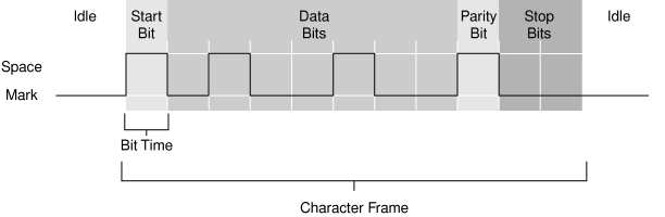 A typical 11-bit serial communication frame, showing start, data, parity, and stop bits.
4. USB-to-TTL Adapter Configuration
To connect the CN2 port to a modern laptop:
- Solder a 4-pin header into the
CN2location on your ECU board. - Connect the GND pin of your USB-to-TTL adapter to the ECU's GND pin (Pin 4).
- Connect the adapter's RX pin to the ECU's TX pin (Pin 1) - cross-connection.
- Connect the adapter's TX pin to the ECU's RX pin (Pin 2) - cross-connection.
- Leave the 5V line disconnected to prevent ground loops, as the USB adapter is powered by the laptop.
- Install the
FTDIor Silicon Labs CP210x drivers on your laptop and select the corresponding COM port in your tuning program.
For details on selecting and troubleshooting the connection hardware, see the USB to serial converter hardware guide. For software plugins, refer to the Crome setup guide.
Credits and source
Authors hondainfo
Source Adapted from Serial Communication on pgmfi.org wiki. Licensed under CC BY-NC-SA 1.0.